

Originally posted in 2012
I’ve been contemplating the use of auto couplings for a number of years, partly because I’m getting older, and my eyesight isn’t what it was 30 years ago, but perhaps the main reason is the reaction of audiences at a show when coupling 3-links takes a bit longer than it might (or more than a few seconds). The big hand descends from the sky with torch and coupling hook, and makes the first attempt at coupling. When this fails, there might be a few muttered words about links being too narrow, or buffers being a bit too long, or whatever. By the third or fourth attempt, accompanied perhaps by a few semi-audible swear words, the audience will start to evaporate.
I think that an exhibition layout should ideally be a piece of theatre, where everything works tolerably well, and whilst there may not always be something moving, at least there shouldn’t be five-minute delays, while three different people have a go at coupling two wagons, before giving up, and taking both the wagons off the layout.
 I’ve looked at various types of auto-
coupling, and for me, AJ’s are the only choice - for two principal reasons. Firstly they are relatively unobtrusive, and secondly they are ‘hermaphrodite’ - ie the couplings on each end of the vehicle are identical, and the stock can be run either way round (important on an end-to-end layout where the stock may get turned).
However, I hadn’t expected the use of AJ’s to be quite such a controversial subject. I’ve had quite a few comments, ranging from ‘never on my stock - I’ll give up railway modelling first’, to ‘why do you build all this stock, and then stick bits of ugly wire on the ends’, and ‘you’ll spend half your life fitting them, and the other half adjusting them’, plus a few less printable comments. It’s true that they are not easy to make or fit, but it can be done - otherwise they wouldn’t have survived for half a century.
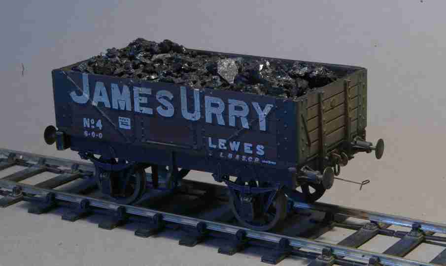
Perhaps my favourite (from a sceptic) was ‘has this wagon got AJ’s on it? - I can’t see them’ (it did).
The main spur to actually getting on with the switchover was the publication of the excellent Scalefour Society book on the subject, and the ready availability of jigs to assist in the making and fixing of the couplings. The book is very comprehensive, and covers pretty much everything in extensive detail, so I haven’t repeated any of this material - I will assume that you will read the book. Here are just a few thoughts on my own experience.
The main points are:
- making the couplings
- fitting the couplings
- why don’t they couple?
- why don’t they uncouple?
- why do they uncouple when they shouldn’t?
- bogie stock
- electromagnets
- what to do first
Making the couplings
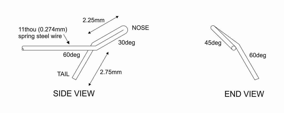
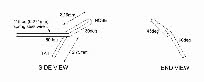 The couplings are made from 11 thou steel guitar string, and their success depends on bending the wire accurately as shown in the diagram, and described more explicitly in the book. There are no specified tolerances for the accuracy of the finished product, but clearly the more accurately they are made, the more likely they are to work. From experience it seems that there is more allowable tolerance on the angles, than on the lengths of the two legs of the coupling. This is convenient, since it’s relatively easy to get the lengths accurate, and rather more difficult to check the absolute accuracy of the angles.
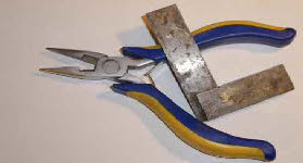
 Palatine models have produced an excellent set of jigs, designed by Graham Turner, for making and fitting the couplings. I have three jigs for making the couplings, shown in the photo. I have tried the multi-
layered etch (‘C’ in the photo), but struggle to make this work as designed and to get all the angles correct, and usually end up making ‘freehand’ adjustments to get the coupling right.
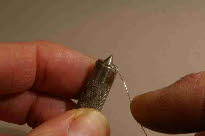
 My preference is to use the two jigs A and B. Jig A has two holes drilled in it -
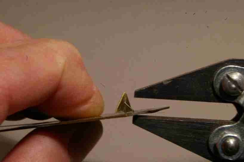
 the first (smaller hole) is used to make the initial 180deg bend, as shown left. (I have filed off the shoulder of the jig so that the first bend can go beyond 90deg, making it easier to complete the 180deg bend). Jig B is then used to complete this first bend, as shown. The instructions for this jig suggest that the ‘wings’ have to be exactly vertical - in fact it’s easier to use if they slope forward slightly, so that the tip of the first bend engages in the jig as shown in the photo (right).
I’ve been contemplating the use of auto couplings for a number of years, partly because I’m getting older, and my eyesight isn’t what it was 30 years ago, but perhaps the main reason is the reaction of audiences at a show when coupling 3-
I think that an exhibition layout should ideally be a piece of theatre, where everything works tolerably well, and whilst there may not always be something moving, at least there shouldn’t be five-
 I’ve looked at various types of auto-
However, I hadn’t expected the use of AJ’s to be quite such a controversial subject. I’ve had quite a few comments, ranging from ‘never on my stock -
Perhaps my favourite (from a sceptic) was ‘has this wagon got AJ’s on it? -
The main spur to actually getting on with the switchover was the publication of the excellent Scalefour Society book on the subject, and the ready availability of jigs to assist in the making and fixing of the couplings. The book is very comprehensive, and covers pretty much everything in extensive detail, so I haven’t repeated any of this material -
The main points are:
-
Making the couplings
 The couplings are made from 11 thou steel guitar string, and their success depends on bending the wire accurately as shown in the diagram, and described more explicitly in the book. There are no specified tolerances for the accuracy of the finished product, but clearly the more accurately they are made, the more likely they are to work. From experience it seems that there is more allowable tolerance on the angles, than on the lengths of the two legs of the coupling. This is convenient, since it’s relatively easy to get the lengths accurate, and rather more difficult to check the absolute accuracy of the angles.
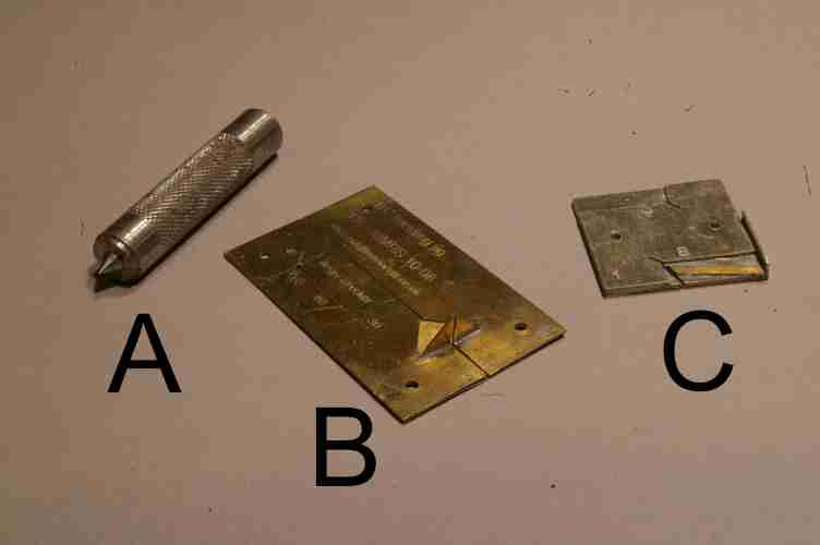 Palatine models have produced an excellent set of jigs, designed by Graham Turner, for making and fitting the couplings. I have three jigs for making the couplings, shown in the photo. I have tried the multi-
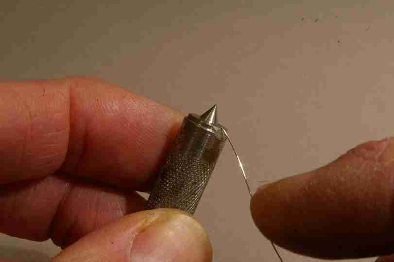
 My preference is to use the two jigs A and B. Jig A has two holes drilled in it -