


Added August 2021
INTRODUCTION
Is scratchbuilding of engines becoming a lost art? When I started modelling over 40 years ago there was little alternative if you wanted to build something slightly out-of-the-ordinary. Even now kits and ready-to-run manufacturers (not surprisingly) focus on well-known, popular models which will sell in reasonable quantity. Scratch-building on the other hand offers the scope to build any class of engine you want: a specific loco from that class, and with whatever variations from standard it may have picked up during its life. And there is the added satisfaction of knowing that your model is unique.
Where to start?
The first requirement is a good drawing, and at least a couple of photographs, one of each side of the chosen engine. Failing that, photographs of engines of the same class, at the same period as your model will suffice.
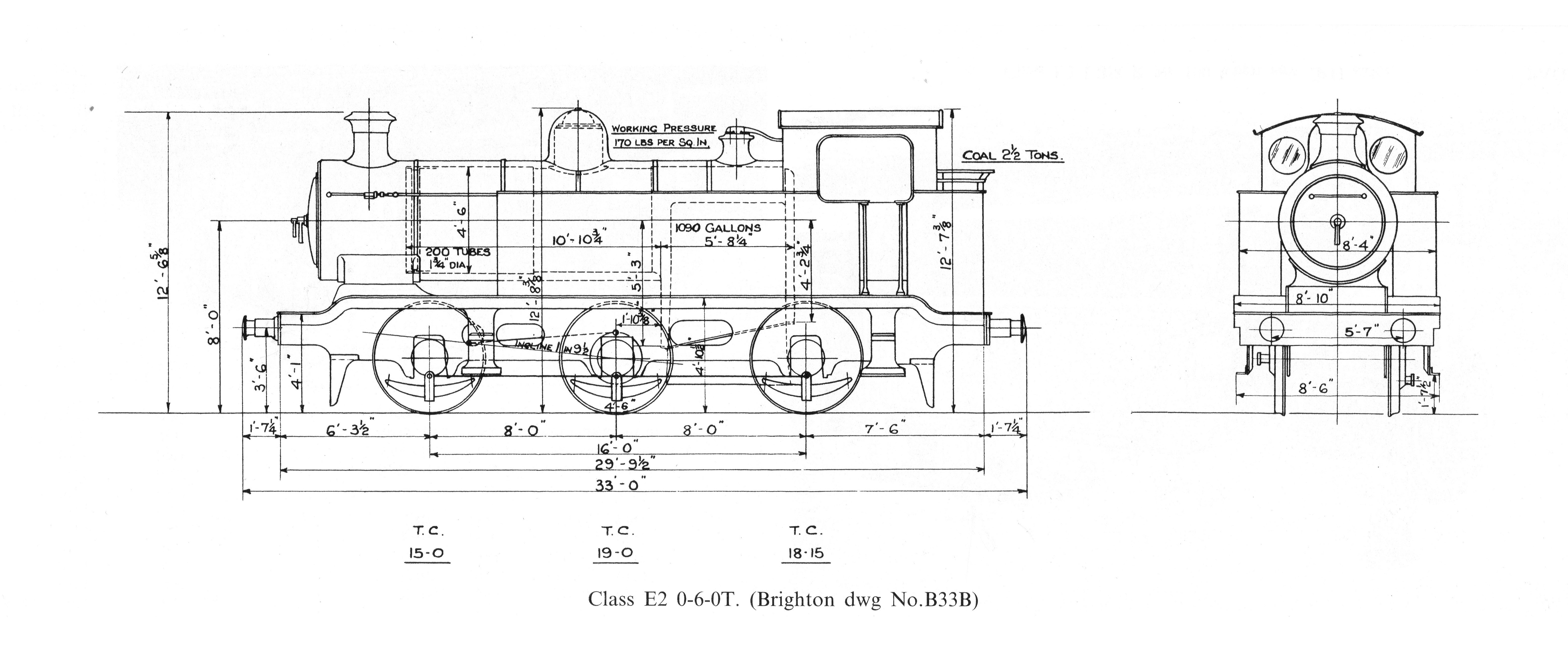
 For the small scales, a weight diagram should be adequate. These give the principal dimensions, and in my experience are sufficiently accurately drawn for other measurements to be scaled off. The LBSCR and Southern are well provided for, and J H Russell’s ‘ A Pictorial Record of Southern Locomotives’ is a particularly good source of information -
 out of print I think, but available second-hand. A full GA can be useful for sorting out details, but can equally be simply confusing because of the amount of detail shown.
 My chosen engine for this project is a Brighton E2 0-
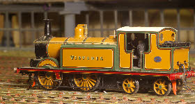
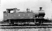
6-0 tank. These were not particularly successful locos, suffering from lack of coal and water capacity which was too small for the intended workings of these engines. They were built to replace the ageing Stroudley E1’s but were not really up to the task, and so were rapidly downgraded to secondary shunting duties. The first batch of E2’s weren’t built until 1913, a little after my chosen period for Plumpton Green, but no worse than my Panter goods brakes and large lettered LBSCR wagons. The photo (left) shows the first of the class in photographic livery.
Tools of the trade
When I built my first scratch-built engine 40 years ago, I had very few tools available - piercing saw, files, steel rule, scribe, vice, drills, and soldering iron. Since then I have inevitably acquired more tools which make the task easier and perhaps quicker, but which are not essential. These are:
INTRODUCTION
Is scratchbuilding of engines becoming a lost art? When I started modelling over 40 years ago there was little alternative if you wanted to build something slightly out-
Where to start?
The first requirement is a good drawing, and at least a couple of photographs, one of each side of the chosen engine. Failing that, photographs of engines of the same class, at the same period as your model will suffice.
 For the small scales, a weight diagram should be adequate. These give the principal dimensions, and in my experience are sufficiently accurately drawn for other measurements to be scaled off. The LBSCR and Southern are well provided for, and J H Russell’s ‘ A Pictorial Record of Southern Locomotives’ is a particularly good source of information -
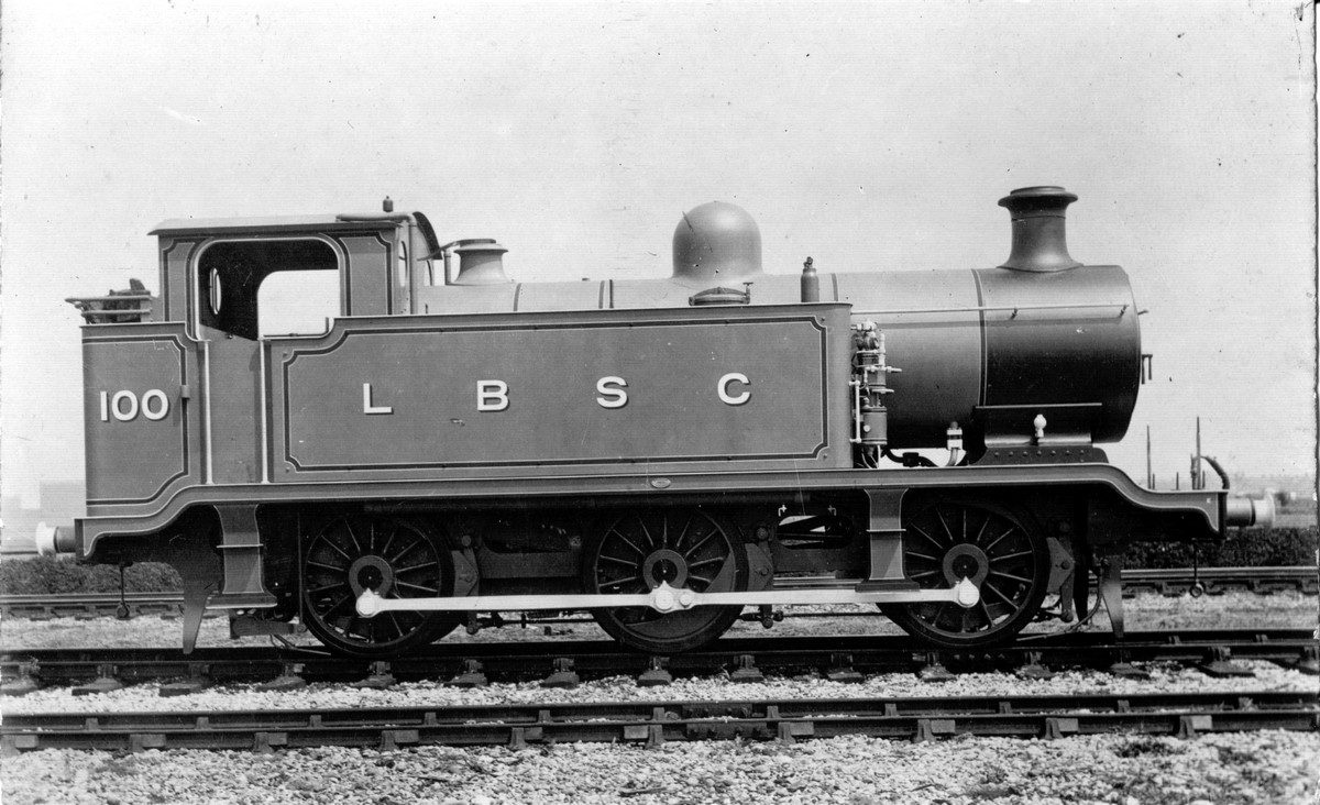 My chosen engine for this project is a Brighton E2 0-
Tools of the trade
When I built my first scratch-
• Guillotine for cutting thin metal (5 and 10 thou)
• Band saw for cutting thicker metal (15 and 18 thou)
• Lathe
• Milling machine/vertical pillar drill
• Numerous clamps and assorted devices for holding things securely
Materials
The best material for building engines is nickel-
For the body of an engine I use mostly 10 thou, with 5 or 6 thou for the boiler, splasher tops and other small details. Unfortunately nickel-
For fittings (chimney, dome, smokebox door etc) I use brass stock turned in the lathe. However, quite a few of these components are available as white metal castings.
I have also resorted to 3D printing for parts not easily available -
Planning
This loco, in common with all the others I have built, will be 4mm:ft, to P4 standards, and fully compensated.
The first task is to assemble all the parts I won’t be making: wheels and coupling rods (Gibson), buffers (Slaters), screwlink coupling (Masokits), motor and gearbox.
There are several ways of compensating an 0-
The E2 chassis has large weight-
My ‘go-
The first stage is to assemble the chassis, to a stage where it is on its wheels, with motor and gearbox in place, and compensation beams fitted and adjusted to get the chassis level and to the correct height. This is described in more detail in the chassis construction section here.
To be continued.