

Ground signals for Brighton Road
 From the modest amount of research I’ve done (mostly trawling through the Signalling Record Society books on LBSCR signalling) it appears the Brighton didn’t have a consistent approach to the use of ground signals. Some locations appear to have a minimalist approach, whilst in other places it seems that virtually every move is signalled. I’ve opted for the latter for Brighton Road, and have ground signals either side of cross-
overs, and for entry and exit to both yards. (The exit from the goods yard is controlled by a shunt ahead arm, allowing trains to leave from the yard, up to the starter).
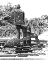
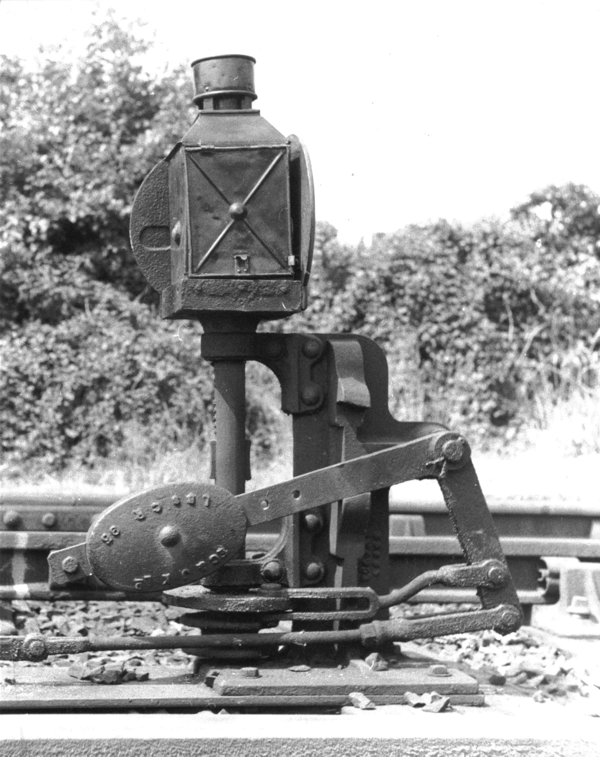
 LBSCR ground signals are of the revolving type, showing a red face when at ‘danger’, and a green face when off. The signals themselves are available from EBModels or from MSE (Wizard models).
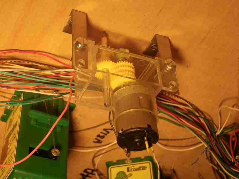
 I’m not aware of any commercially available rotating actuators (apart from the recent innovation using radio control aircraft actuators) so I made my own, using ‘Clearbox’ motors as the basis. These are useful motors, running on 3-
6V, and with cleverly designed gearboxes which can be arranged to give a very wide range of gear ratios. However, these motors don’t have a stop mechanism to allow them to turn through 90deg, and stop automatically.
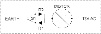 I have a 15V AC supply on the layout, and I use this for motors which need to be run in both directions (turnouts, signals, gates). The basic principle of the electrics is shown in the diagram. Diodes are used to give half-
wave rectification - positive when the switch S1 is thrown in one direction (via diode D1), and negative when thrown in the opposite direction (via diode D2). The motor will therefore run either forwards or backwards, depending on the position of switch S1.
However, this doesn’t provide an automatic stop when the signal has rotated through 90deg. It works ok for a gate for example, when you can see clearly how far the gate has moved, but not for my ground signals, where they need to move reliably back and forth through 90deg. (For gates I have used a single pole switch, sprung to centre, so that the motor stops when the switch us released).
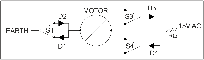 The second diagram shows two additional switches and associated diodes (S3, D3 and S4, D4). These switches are micro-
switches attached to the motor gearbox, and are actuated by a lever (a long bolt) fixed to the motor spindle. When the signal is in the middle of its travel, both S3 and S4 are closed, and current will flow through whichever one it can (ie the one with the diode in the same direction as switch S1). When the motor gets to one end of its travel, and opens one of the microswitches (S4 in the diagram) the motor will stop, because current cannot flow through diode D1, and the opposing diode D3. However, if the main switch S1 is reversed, then current can again flow (but with opposite polarity through D2 and D4) and the motor will run in reverse until switch S3 is opened by the movement of the motor. I have used a small resistor to step down the voltage to about 3-4V.
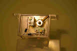
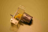
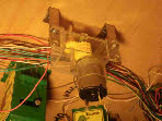
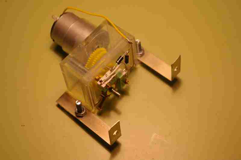
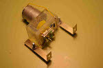 The photos show the micro-
switches attached to the motor, and the assembly with brackets added to fit it under the base-board. The motor shaft is connected to the signal using a short piece of flexible tube.
Brighton Road has control panels separate from the layout, so switch S1, is on the control panel, and only a single wire to the layout is required to operate each signal.
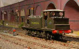
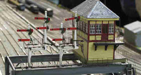
 The final two photos shows a ground signal above and below the baseboard.
 From the modest amount of research I’ve done (mostly trawling through the Signalling Record Society books on LBSCR signalling) it appears the Brighton didn’t have a consistent approach to the use of ground signals. Some locations appear to have a minimalist approach, whilst in other places it seems that virtually every move is signalled. I’ve opted for the latter for Brighton Road, and have ground signals either side of cross-
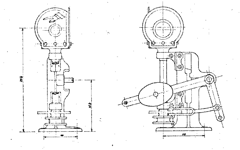 LBSCR ground signals are of the revolving type, showing a red face when at ‘danger’, and a green face when off. The signals themselves are available from EBModels or from MSE (Wizard models).
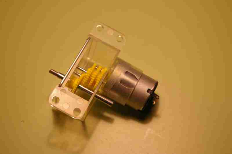 I’m not aware of any commercially available rotating actuators (apart from the recent innovation using radio control aircraft actuators) so I made my own, using ‘Clearbox’ motors as the basis. These are useful motors, running on 3-
 I have a 15V AC supply on the layout, and I use this for motors which need to be run in both directions (turnouts, signals, gates). The basic principle of the electrics is shown in the diagram. Diodes are used to give half-
However, this doesn’t provide an automatic stop when the signal has rotated through 90deg. It works ok for a gate for example, when you can see clearly how far the gate has moved, but not for my ground signals, where they need to move reliably back and forth through 90deg. (For gates I have used a single pole switch, sprung to centre, so that the motor stops when the switch us released).
 The second diagram shows two additional switches and associated diodes (S3, D3 and S4, D4). These switches are micro-
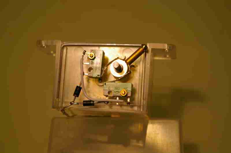
 The photos show the micro-
Brighton Road has control panels separate from the layout, so switch S1, is on the control panel, and only a single wire to the layout is required to operate each signal.
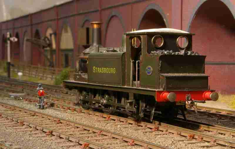
 The final two photos shows a ground signal above and below the baseboard.