

Last updated May 2023
Ground signals
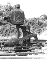
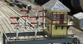
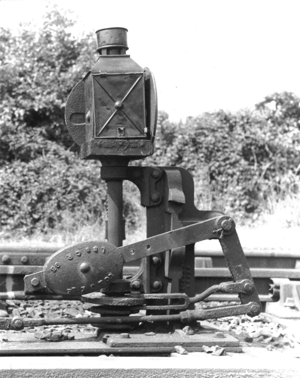
 LBSCR ground signals are of the revolving type, showing a red face when at ‘danger’, and a green face when off. The signals themselves are available from EBModels or from MSE (Wizard models).
For the various layouts I have been involved with, I have tried several different approaches to motorising these signals. My approach for Brighton Road is described below, but I have tried three other alternatives for Plumpton Green.
Ground signals for Plumpton Green
 My first approach was to use Fulgurex motors, as being cheaper than Tortoises. However, these proved very noisy in operation, and with the demise of Brighton Road, I had a large number of spare Tortoises, so out went the Fulgurex motors. The Tortoises have a relatively short throw, not really enough to rotate a ground signal through 90 deg, so I added a lever to double the amount of movement. This proved reasonably successful, but there was a fair amount of slop in the mechanism, which meant that adjustment of the signal’s rotation was not easy.
Following my success with electronics and servos for the level crossing gates (see here), it seemed worth looking at moving on yet again, and converting all ground signals to servo operation.
The Model Electronics Railway Group (MERG) sells a range of products which make this approach very easy. Servos are not like ordinary motors - their position is not dependent on voltage, but by sending them an electrical pulse of variable width. The angle of rotation of the servo is determined by the duration of a pulse that is applied to the control wire. The servo expects to see a pulse every 20 ms. The length of the pulse will determine how far the motor turns. For example, a 1.5 ms pulse will make the motor turn to the centre position, whilst 1ms or 2ms pulses will make the servo turn to the extremities of its rotational range, either side of centre.
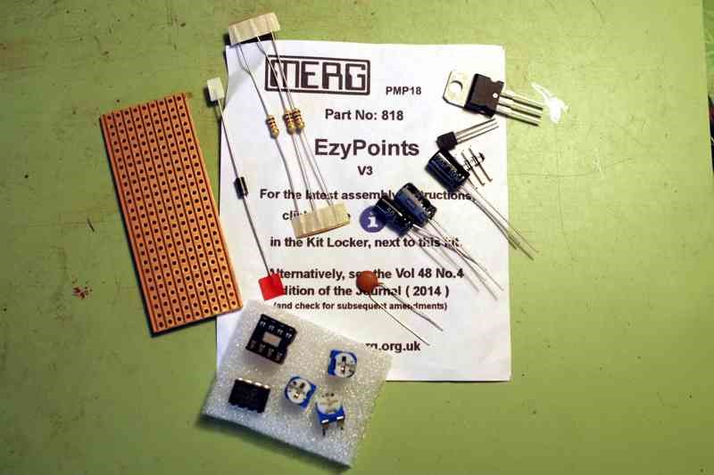
MERG sell two electronic kits for controlling servos, the ‘EZYpoints’ kit and the ‘Servo4’ kit. Both are easy to make (less than an hour, once you understand what’s required). For the usual radio-control purposes, the angle of rotation of the servo is variable, and controlled by the operator via the radio transmitter. Both the MERG units give only two end points, together with control of the speed of rotation between the two end-points. These three parameters are fully adjustable, and once set up, all that is required to move the servo between the two end points is a switch to earth, controlled in the case of Plumpton Green by a relay triggered from the lever frame The differences between the two MERG units are outlined here:
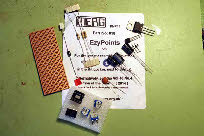 The EZYpoints kit controls only a single servo; is set up (extremities of movement, and speed of rotation) using a screwdriver; can be easily adjusted to give more than 90deg rotation; and requires a regulated 12v DC power supply.
The Servo4 unit can control up to four servos; requires either a laptop (with MERG-supplied software) or a ‘Servoset2’ kit to set it up; as-built it can only drive servos through 90deg maximum, although the unit can be re-programmed to give about 180 deg; and requires a 9v AC or 12v DC supply (although this can be changed as described below).
For the level crossing gates, I used four EZYpoints kits, principally because two of the gates require more than 90deg movement and this is easily accommodated by the EZYpoints kit. For signals I am using the servo4 kit, mainly because it’s easier to make and fit one unit for four signals rather than making four separate modules.

 As stated above, the Servo4 kit requires an input voltage of either 9v AC or 12v DC. With the exception of the board with the level crossing on it (which has a dedicated 12v DC supply for the gates), I have either 15v AC or 21v DC supplies -
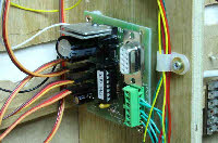
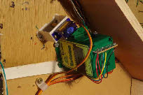
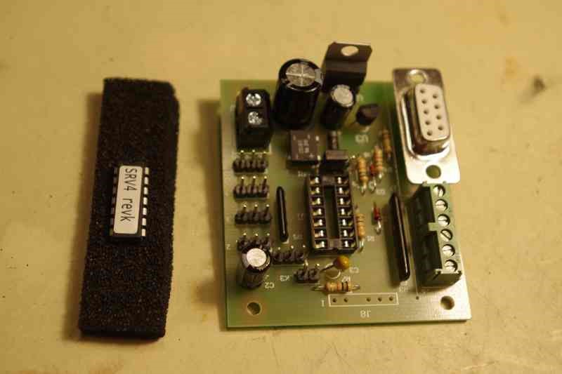
 too high for the Servo4. However, a couple of questions on the MERG forum elicited an easy solution - replace the 15v capacitor at the input with a larger capacitor, and add more heat-sink to the 12v regulator to ensure it doesn’t burn out. The photo on the left shows the original design, and the photo on the right shows the substitution of the larger capacitor (25v, 2200mf, supplied separately by MERG) and the addition of the aluminium heat-sink to the voltage regulator. This unit now works very satisfactorily off the 21v DC supply, which saves me having to wire a new 12v DC supply through the layout. (These modifications can also be applied to the 12V regulated supply kit, so that they can be fed from a 21V supply, to run a single EZYpoints unit for example).
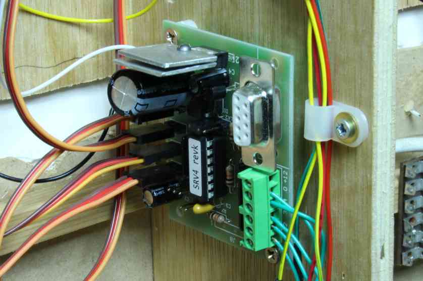
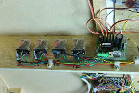 To actuate the servo all that is required is to switch to earth the appropriate tag on the green terminal (bottom right on the photo above). The photo (right) shows the Servo4 unit and its four relays, which are activated by micro switches on the lever frame.
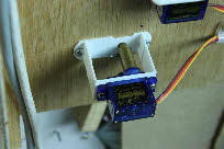
 The servos are mounted on modified MERG servo mounts, described as ‘level crossing gate servo mounts’ but which are applicable to anything which rotates about a vertical axis -
 gates, cranes, and LBSCR ground signals for example. There are also various designs for semaphore signals which can be seen here. The photo shows one of the ground signal servos, and for comparison shows the size of the adjacent Tortoise point motor.
 The photo (right) leads to a short video, showing the modified servo mount, and brass adaptor which connects to the ground signal.
Ground signals
 LBSCR ground signals are of the revolving type, showing a red face when at ‘danger’, and a green face when off. The signals themselves are available from EBModels or from MSE (Wizard models).
For the various layouts I have been involved with, I have tried several different approaches to motorising these signals. My approach for Brighton Road is described below, but I have tried three other alternatives for Plumpton Green.
Ground signals for Plumpton Green
 My first approach was to use Fulgurex motors, as being cheaper than Tortoises. However, these proved very noisy in operation, and with the demise of Brighton Road, I had a large number of spare Tortoises, so out went the Fulgurex motors. The Tortoises have a relatively short throw, not really enough to rotate a ground signal through 90 deg, so I added a lever to double the amount of movement. This proved reasonably successful, but there was a fair amount of slop in the mechanism, which meant that adjustment of the signal’s rotation was not easy.
Following my success with electronics and servos for the level crossing gates (see here), it seemed worth looking at moving on yet again, and converting all ground signals to servo operation.
The Model Electronics Railway Group (MERG) sells a range of products which make this approach very easy. Servos are not like ordinary motors -
MERG sell two electronic kits for controlling servos, the ‘EZYpoints’ kit and the ‘Servo4’ kit. Both are easy to make (less than an hour, once you understand what’s required). For the usual radio-
 The EZYpoints kit controls only a single servo; is set up (extremities of movement, and speed of rotation) using a screwdriver; can be easily adjusted to give more than 90deg rotation; and requires a regulated 12v DC power supply.
 The Servo4 unit can control up to four servos; requires either a laptop (with MERG-
For the level crossing gates, I used four EZYpoints kits, principally because two of the gates require more than 90deg movement and this is easily accommodated by the EZYpoints kit. For signals I am using the servo4 kit, mainly because it’s easier to make and fit one unit for four signals rather than making four separate modules.
 As stated above, the Servo4 kit requires an input voltage of either 9v AC or 12v DC. With the exception of the board with the level crossing on it (which has a dedicated 12v DC supply for the gates), I have either 15v AC or 21v DC supplies -
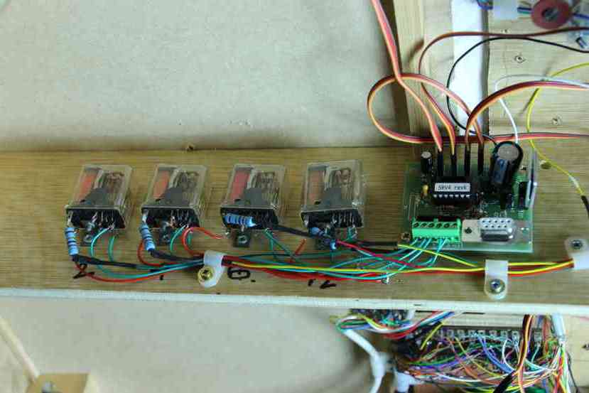 To actuate the servo all that is required is to switch to earth the appropriate tag on the green terminal (bottom right on the photo above). The photo (right) shows the Servo4 unit and its four relays, which are activated by micro switches on the lever frame.
 The servos are mounted on modified MERG servo mounts, described as ‘level crossing gate servo mounts’ but which are applicable to anything which rotates about a vertical axis -The photo (right) leads to a short video, showing the modified servo mount, and brass adaptor which connects to the ground signal.