

Last updated May 2023
Running signals for Plumpton Green
Tortoise motors are not ideal for operating semaphore signals, and my attempts to get reliable operation have been a bit Heath-Robinson-ish, and not entirely successful. Having successfully mastered the building of MERG electronics units for the level crossing gates, I decided that servos would be much simpler.
I’ve now converted all ground signals to servos (shown here, with more information on electronics and servos) with much improved operation - easier to set up and adjust, as well as being more robust.
 For semaphore signals the same applies -
 more robust and easier to adjust, but the difficulty is that the movement of the pull-rod to pull the signal ‘off’ is very small - about a millimetre. It is not possible to get such a tiny movement from the servo control link, with the fine adjustment needed to get the signal’s ‘on’ and ‘off’ positions right, or to get a reasonable speed of movement of the arm. The servo is capable of rotating at least 90 deg, and to get reasonably fine adjustment of ‘on’ and ‘off’ positions and speed of movement, most of this rotary movement needs to be utilised. Also the rotary movement of the servo has to be converted to vertical movement.
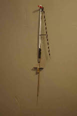
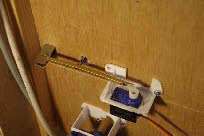 The photo (left) shows my mechanism -
 a lever arranged with the servo at one end, and the signal pull rod about 1/3 of the distance from the lever pivot. I have shortened the control link on the servo so that it effectively operates as a cam, lifting the lever by a relatively small amount for about 45 deg of rotary movement. The mechanics of the lever reduces this movement of the pull rod by about 1/3, giving the necessary 1mm or so, and allowing the fine adjustment needed.
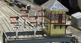
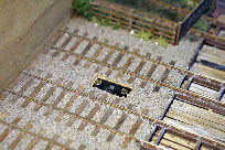 The semaphore signals are fitted into brackets which are screwed to the base-
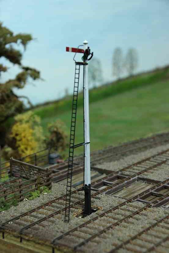
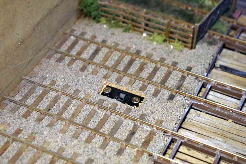
board, as shown in the photos (right), prior to ballasting. The post is a tight fit in the square tube so it does not need to be permanently fixed in place and can be relatively easily removed if needed.
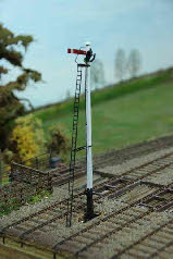
 This particular signal is the down home, and the last to be fitted to the layout. It is situated on the embankment, hence the need for the very long operating wire (to reach the underside of the baseboard). The small diameter tube fitted to the bracket accommodates the operating wire to keep it straight.
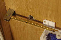 The compression spring shown in the photo (right) pulls the signal ‘off’, and the action of the servo lifting the lever puts the signal ‘on’. It would be preferable for the spring to return the signal to ‘on’, but that would have been rather more complex to arrange.
There is a very short video here, showing the signal and its operating mechanism in action.
For the running signals I’ve used both EZYpoints and Servo4 units (described in more detail on the page about ground signals), and both work well. These units have been modified so that they can be powered from the 21V DC supply (as described here). The switching mechanism for each servo is triggered by a relay connected to a microswitch on the lever frame, and activated by the appropriate lever.
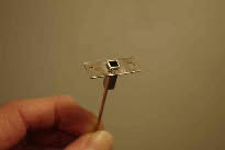
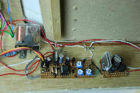 The photo (left) shows the EZYpoints kit for this signal, powered by a modified 12v supply, with the relay which provides the switch to earth and activates the servo
Running signals for Plumpton Green
Tortoise motors are not ideal for operating semaphore signals, and my attempts to get reliable operation have been a bit Heath-
I’ve now converted all ground signals to servos (shown here, with more information on electronics and servos) with much improved operation -
 For semaphore signals the same applies -
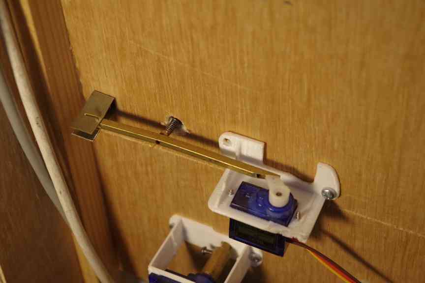 The photo (left) shows my mechanism -
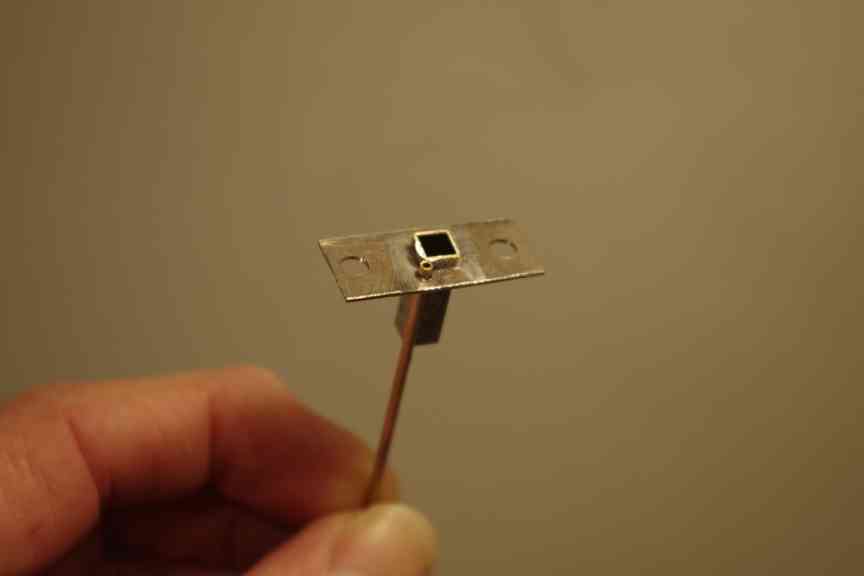
 The semaphore signals are fitted into brackets which are screwed to the base-
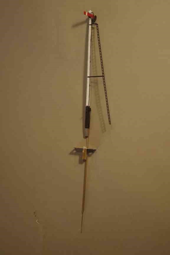 This particular signal is the down home, and the last to be fitted to the layout. It is situated on the embankment, hence the need for the very long operating wire (to reach the underside of the baseboard). The small diameter tube fitted to the bracket accommodates the operating wire to keep it straight.
 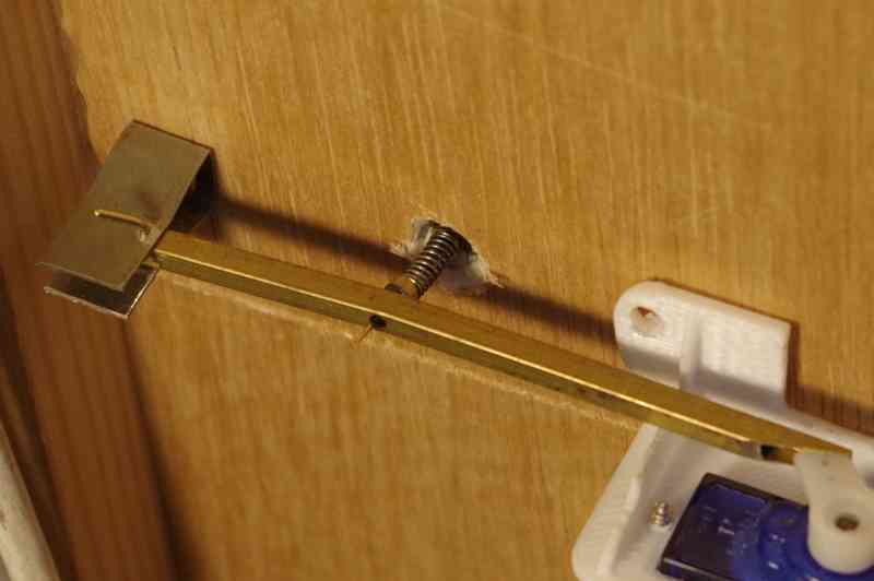 The compression spring shown in the photo (right) pulls the signal ‘off’, and the action of the servo lifting the lever puts the signal ‘on’. It would be preferable for the spring to return the signal to ‘on’, but that would have been rather more complex to arrange.
 There is a very short video here, showing the signal and its operating mechanism in action.
For the running signals I’ve used both EZYpoints and Servo4 units (described in more detail on the page about ground signals), and both work well. These units have been modified so that they can be powered from the 21V DC supply (as described here). The switching mechanism for each servo is triggered by a relay connected to a microswitch on the lever frame, and activated by the appropriate lever.
 The photo (left) shows the EZYpoints kit for this signal, powered by a modified 12v supply, with the relay which provides the switch to earth and activates the servo