


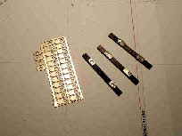
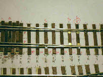
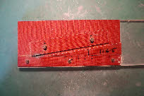
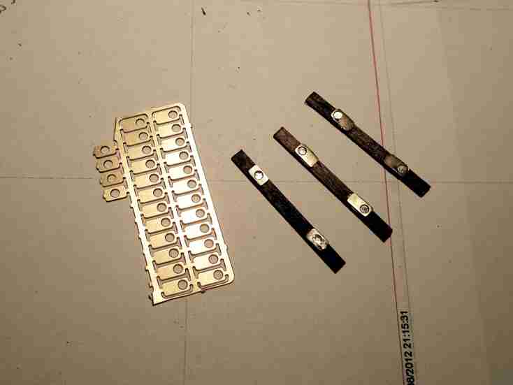
 For slide chairs on Brighton Road we used C&L plastic ones, but these have two drawbacks - firstly the stock rails are not fixed very firmly along their length over the slide chairs which can give problems with gauge tolerance, and secondly plastic chairs are a bit vulnerable to heat damage when soldering in the tie bars, or repairing them. For Plumpton we have used a few of Bill Bedford's brass slide chairs, either side of the tie-bar, and at intervals of every third or forth sleeper. Hopefully this will overcome any problems. The two photos show, on the left, part of the etch, and three sleepers showing how the etches solder over rivets, and on the right, the sleepers in place on a turnout.
If I had discovered these a little earlier in the process, I would have used them under crossing V’s and check rails, in place of my glued efforts.
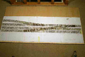 Finally we have all the boards completed - rails soldered in place, functional and cosmetic chairs glued in, and slide chairs fitted. The final stage before laying the track is to add the tie bars, and paint the sides of all the rails.
Having built the baseboards, we decided to lay the track on a conventional 1/8 inch cork base. A friend recommended using flooring adhesive to glue the track, because it remains flexible, and in his opinion reduces noise. It also has the advantage that because it dries much more slowly than PVA, the track can be aligned and ballasted in one hit, rather than ballasting as a separate (and very slow) process.
It is certainly true that this technique enables track to be laid and ballasted much more quickly than ballasting as a separate process. However, I’m not convinced that the layout is any quieter - certainly not in the context of a railway exhibition. The biggest drawback of this method is that even after 10 years, the glue is still pliable, with the result that a couple of rail-end sleepers have had a tendency to move very slightly causing derailments. These have now been more firmly fixed to the cork.
Ouse Wharf
For Ouse Wharf we will be using the same method using plywood sleepers, and a combination of rivets and functional chairs.
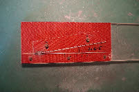
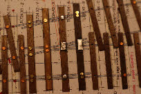 For point-work, instead of gluing nickel-silver strips to the sleepers under the ‘V’, I have made some nickel-silver strips (similar to the Bill Bedford slide chairs described above) with a hole drilled through in an appropriate place, so that they can be soldered over a rivet, providing a more secure fixing than just gluing, as shown in the photo right.
The only other change is that we have filed flat the underside of each riveted sleeper. This may seem trivial, but I have a suspicion that on Plumpton some of the rivets were not pressed absolutely flat under the sleeper, giving rise to some minor uneven-ness in the rail level.
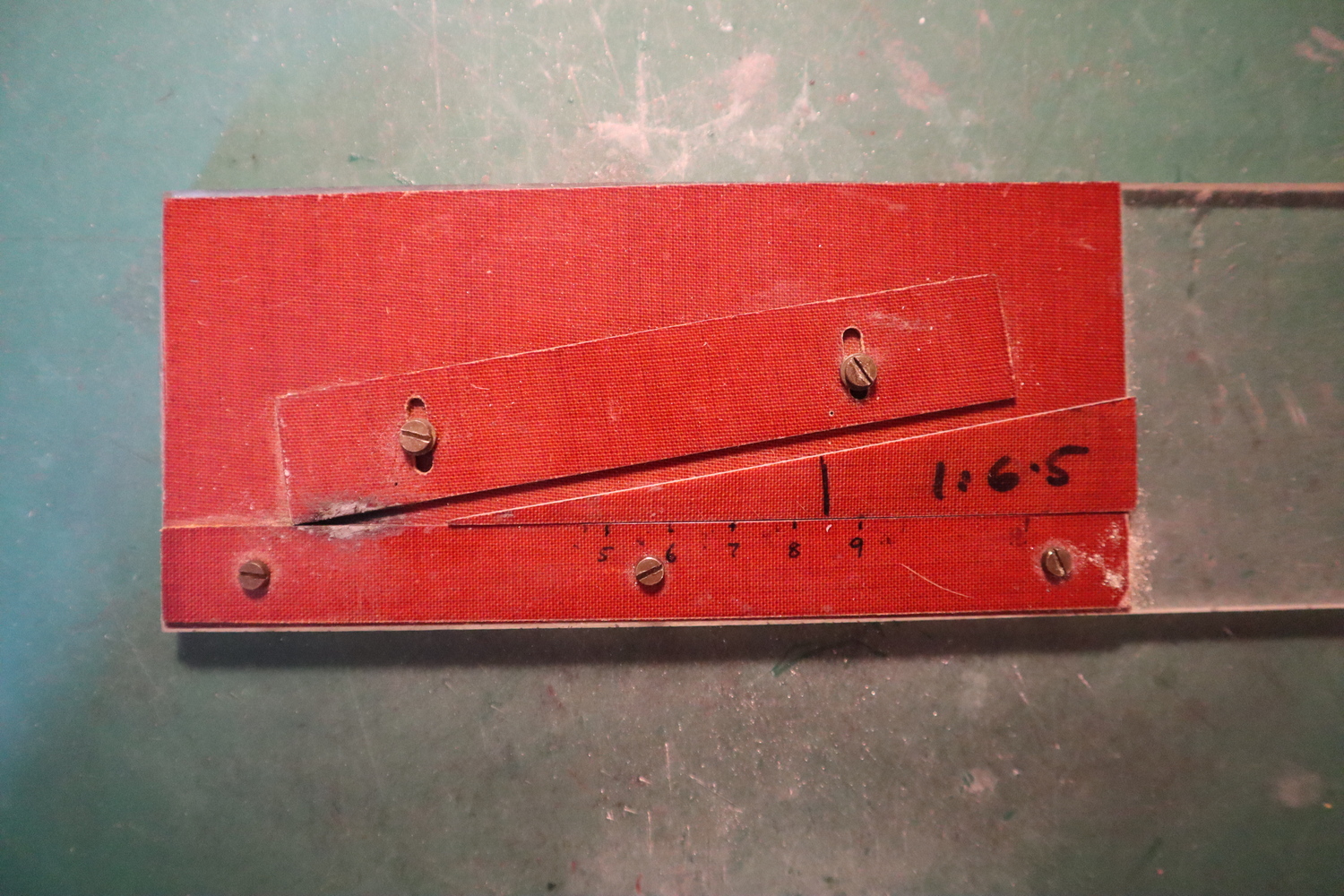
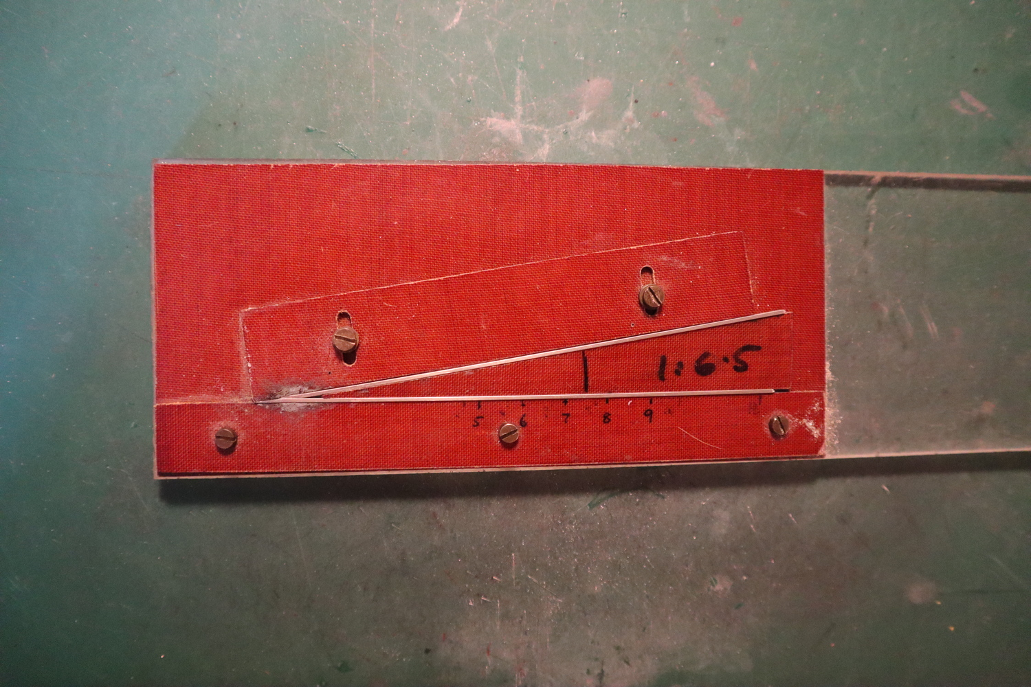
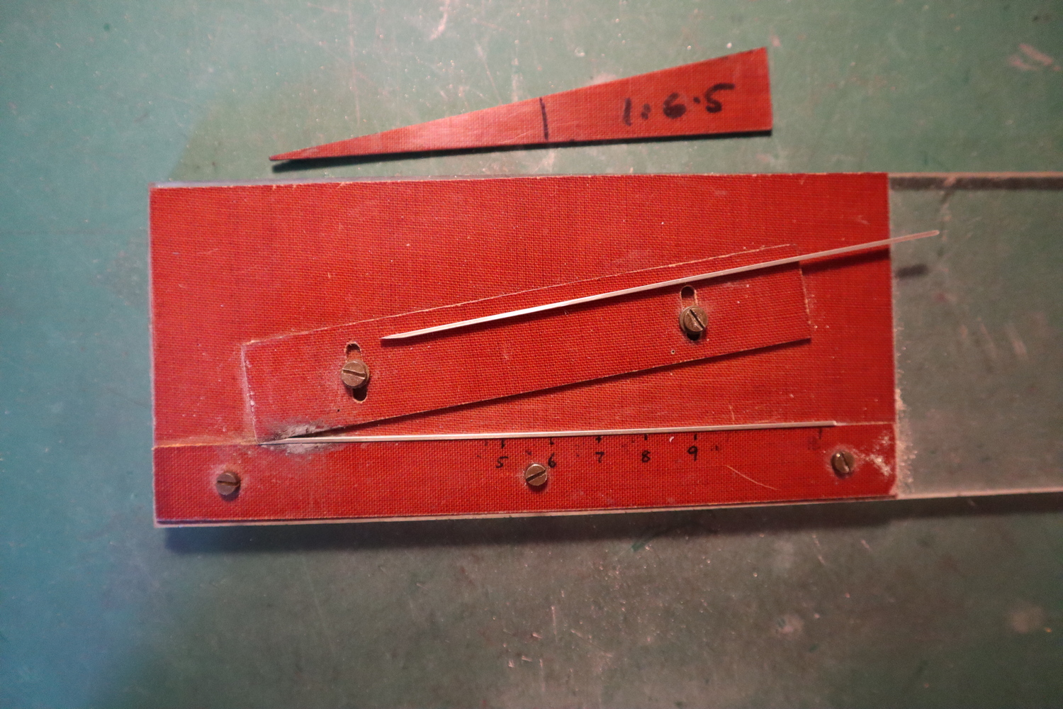
For this layout we’ve used switch blades from C&L, which takes a lot of effort out of building pointwork (although not cheap). For the V’s we have reverted to making them from scratch, using a jig I made about 40 years ago when we were building Pulborough. The jig is shown in the photos below, and it is hopefully self-evident how it is used. It is made of Tufnol, mounted on a piece of acrylic. I have made a number of templates of various crossing angles from 1:5 to 1:9 - the 1:6.5 is shown in the photo. The upper part of the jig is adjustable to fit the required angle. The two rails which make up the V are made as described in the Scalefour manual, filed to fit the required crossing angle. They are then held in place with the template whilst being soldered.


 For slide chairs on Brighton Road we used C&L plastic ones, but these have two drawbacks -
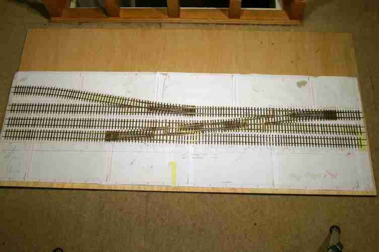 Finally we have all the boards completed -
 For point-