

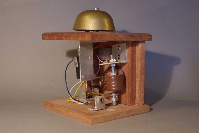
The second photo shows the innards. In this photo the bell has been removed to show the clapper.
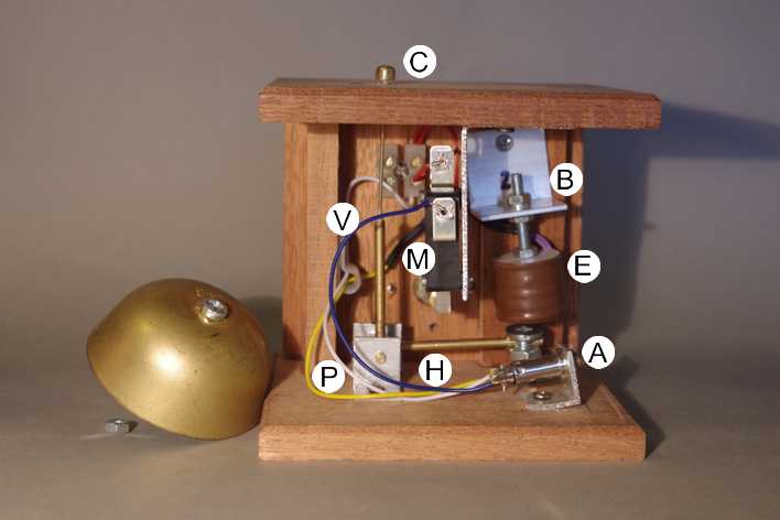
The only moving part is the ‘L’ shaped lever, consisting of a horizontal arm ‘H’ and the vertical arm ‘V’ connected together at the pivot ‘P’. The horizontal part of the lever is made from 1/8” brass rod, fixed to the pivot. At its outer end is the armature ‘A’ which consists of a steel bolt with a shank diameter of 6mm, which has been drilled through at 1/8” diameter. This allows the bolt to be slid onto the brass rod, and the armature is held in place by tightening the nut against the rod.
The armature is pulled upwards by the force of the electromagnet at ‘E’. The core of the electromagnet is a steel bolt, and this is fitted through the bracket at ‘B’ with two nuts, so that the magnet can be raised or lowered by adjusting the positions of the nuts on the screw thread.
 The vertical arm of the lever ‘V’ is made up of two parts -
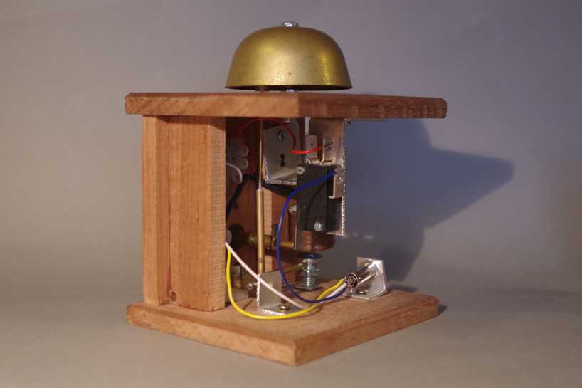
 the lower half is 1/8” brass rod, whilst the upper half is springy 1mm brass wire, soldered into a hole drilled into the end the of the brass rod section. At its upper end is the clapper ‘C’, made of 6mm brass rod, turned to a suitable shape, drilled and soldered to the top of the brass wire. When I first made these boxes, I used cheap push-to-make switches, but these proved unreliable. I have subsequently replaced them with brass plungers (made on my lathe) which act on the microswitch ‘M’. The final two photos show three-quarter views which may help to see what fits where.
In action the electromagnet pulls the armature upwards, which moves the clapper leftward to strike the bell. When the plunger is released, the lever returns to its starting position under gravity - there are no springs to adjust or break. The ‘L’ shaped lever makes this much easier than a straight vertical lever, and is also more compact. The armature performs a secondary function as a weight to ensure that the lever returns to normal. The weight can be adjusted by adding more nuts or washers, or reduced by using thinner nuts, for example.
The electromagnet can be easily adjusted up or down to bring it within range of the armature to make sure that it functions properly, and it also acts as an upward stop when power is applied to the magnet.
The crucial element is that the clapper must strike the bell, and then immediately retract otherwise the bell will ‘clunk’ rather than ring. Simply releasing the plunger is not quick enough, and instead of the bell continuing to ring after it has been struck, you will therefore just get the clunk - or nothing at all. The purpose of the two part vertical arm is thus to provide a very small amount of spring - when the armature hits the magnet core, the rigid parts of the L lever stop, but the clapper has enough momentum to carry it forward on the springy wire to strike the bell (a fraction of a millimetre) and to then retract allowing the bell to ring. Releasing the plunger then allows the lever to drop under gravity to its starting position ready for the next bell stroke.
The bells I have used are old-fashioned BT telephone bells, bought from ebay for a couple of pounds a pair. One very useful feature that came to light when fitting the bells is that the hole for the support pillar is not central, relative to the perimeter of the bell. This provides the ideal mechanism for fine-tuning the bell. Coarse adjustment can be made to the clapper position simply by bending the 1mm wire to suit. It can be set up so that in one extreme position of the bell, the clapper does not strike the bell at all, and then when the bell is rotated 180deg the clapper strikes the bell with a clunk. Somewhere between these two extremes is the ideal - simply rotate the bell a few degrees, press the plunger and repeat until the clapper is just close enough to hit the bell and retract to allow it to ring.
The electromagnets were originally bought for use as AJ magnets on Pulborough, but were never fitted. They were subsequently fitted to Brighton Road where they worked tolerably well. Now that Brighton Road is no more, they have a new lease of life. They were designed to operate at around 6-12V DC, for up to a minute, without overheating. Given that in their new use they are only powered up for a fraction of a second for each bell stroke, I have pushed the voltage to 21v DC, to give much more power. None have melted yet, after continuous use at many shows over the past ten years.
Returning to the theme of irritating bells at exhibitions, these bells are fairly quiet, but in any event it seems self evident that the spectator should hear only one set of bells (ie the Plumpton box in my case) and shouldn’t also be able to hear the bells ringing on the fiddle yards - they are supposed to be several miles away! In practice this has proved to be the case.
The only moving part is the ‘L’ shaped lever, consisting of a horizontal arm ‘H’ and the vertical arm ‘V’ connected together at the pivot ‘P’. The horizontal part of the lever is made from 1/8” brass rod, fixed to the pivot. At its outer end is the armature ‘A’ which consists of a steel bolt with a shank diameter of 6mm, which has been drilled through at 1/8” diameter. This allows the bolt to be slid onto the brass rod, and the armature is held in place by tightening the nut against the rod.
The armature is pulled upwards by the force of the electromagnet at ‘E’. The core of the electromagnet is a steel bolt, and this is fitted through the bracket at ‘B’ with two nuts, so that the magnet can be raised or lowered by adjusting the positions of the nuts on the screw thread.
 The vertical arm of the lever ‘V’ is made up of two parts -
In action the electromagnet pulls the armature upwards, which moves the clapper leftward to strike the bell. When the plunger is released, the lever returns to its starting position under gravity -
The electromagnet can be easily adjusted up or down to bring it within range of the armature to make sure that it functions properly, and it also acts as an upward stop when power is applied to the magnet.
The crucial element is that the clapper must strike the bell, and then immediately retract otherwise the bell will ‘clunk’ rather than ring. Simply releasing the plunger is not quick enough, and instead of the bell continuing to ring after it has been struck, you will therefore just get the clunk -
The bells I have used are old-
The electromagnets were originally bought for use as AJ magnets on Pulborough, but were never fitted. They were subsequently fitted to Brighton Road where they worked tolerably well. Now that Brighton Road is no more, they have a new lease of life. They were designed to operate at around 6-
Returning to the theme of irritating bells at exhibitions, these bells are fairly quiet, but in any event it seems self evident that the spectator should hear only one set of bells (ie the Plumpton box in my case) and shouldn’t also be able to hear the bells ringing on the fiddle yards -