

Block instruments
Having successfully got the block bells operational at the Epsom and Ewell show, the block instruments were the next project.
There are many types of block instruments, which show the status of the line between two signal boxes - the ‘block’. I’ve chosen to use Tyer’s two-position instruments, which were used extensively on the Brighton system. They are ‘two-position’ because they show only ‘line clear’ and ‘line blocked’, whereas later instruments had a third indication showing ‘train-on-line’ as distinct from ‘line blocked’.
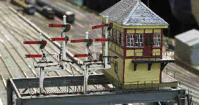
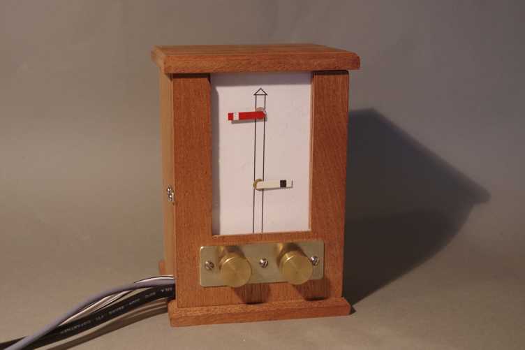
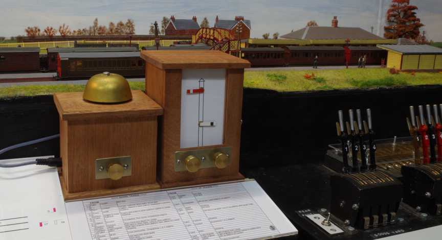
There is a Tyer’s instrument in the Bluebell’s museum at Sheffield Park. The face of the instrument shows a signal post with two signal arms - red and white. The white arm is a repeater for the miniature red arm on the instrument in the box in rear (ie they both operate together). There are three plungers: bell only; bell plus ‘line clear’ indication; bell plus ‘line blocked’ indication.
The ‘official’ instructions for use of these instruments are as follows. The letters ‘A’, ‘B’ and ‘C’ refer to three signal boxes in succession.
(a) Prior to the dispatch of a Train from “A” the Signalman there, provided he has received the Train Out of Section Signal from the previous Train and the Block Instrument is in its normal position, must call the attention of “B” on the Bell Key, and having obtained it must give the proper Is Line Clear Signal on the Bell Key. If the line be clear at “B” the signalman there must acknowledge the Signal on the Clear Key which will lower the white semaphore arm at “B” and the red arm at “A” to the Line Clear position.
(b) On the Train leaving “A” the Signalman there must send the Train Entering Section Signal on the Bell Key to “B”, who must acknowledge the signal on the Block Key which will raise the white arm at “B” and the red arm at “A” to the Line Blocked position.
(c ) “B” must then, provided he has received the Train Out of Section Signal for the previous Train and the Block Indicator is in its normal position, call the attention of “C”, and having obtained it must give the proper Is Line Clear Signal to “C”. If the line be clear “C” will give permission for the train to approach. As soon as the train has arrived at or passed “B” or been shunted clear of the main line at “B”, the Signalman there must give the Train Out of Section Signal to “A” on the Bell Key, which “A” must acknowledge.
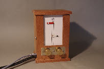 The photo shows one of the instruments. The Line Clear plunger is on the left, and the Line Blocked plunger on the right. The Bell Key is separate, on bell box, shown on previous pages.
In use on Plumpton, the only change is that when the fiddle yard operator asks ‘is line clear’, this indicates that the next train in the sequence is ready to go, but that the cassette is not yet electrically connected to the power. When the Plumpton box acknowledges ‘is line clear’, this indicates that the cassette can be connected, and when the fiddle yard operator sends ‘train entering section’ this indicates that the cassette is electrically connected. This doesn’t represent permission to drive onto the layout - that is still dependent on signals being pulled off.
When a fiddle yard operator, having received a train, sends ‘train out of section’ this indicates that the cassette has been electrically disconnected.
There are two pairs of boxes, one between Plumpton and the Keymer Junction-end fiddle yard, and the other between Plumpton and the Lewes-end fiddle yard.
There have been several articles in the model railway press outlining methods of making block instruments, mostly using ammeters or voltmeters to provide the indications. I have chosen a rather different approach, using servos to operate the miniature arms on the Tyer’s instruments. This is possible with two position instruments, but possibly not when three positions are required.
The basic principle of my instruments is the use of a MERG (Model Electronics Railway Group) ‘Servo4’ driver. This circuit (supplied as a kit) is capable of driving four independent servos, each with its own setting of ‘on’, ‘off’, and speed of rotation in each direction. In each pair of my instruments there are four miniature arms, each with a servo, and hence one servo4 unit is sufficient for one pair of instruments. Once the servo on and off positions have been set it requires only a simple switch to toggle the servo between its two preset positions. (The servo positions and speeds are set using either a laptop with MERG software, or a MERG ‘Servoset2’ kit).
The ‘line clear’ plunger at the Plumpton box acts on a microswitch, which rings the bell on the fiddle yard box and also pulls in the relay. The relay is wired to latch (ie stay on) when the plunger is released. The relay then acts as the switch for two of the servos which move the miniature signals (the red one on the fiddle yard instrument, and the corresponding white one in the Plumpton box) to the off position. The ‘line blocked’ plunger rings the bell and un-latches the relay, so that the two arms return to their ‘on’ position. (Slightly confusing, because when the servos are in their ‘on’ position, the signals show the ‘off’ position, and vice versa).
Similarly the two plungers in the fiddle yard box act on another relay, which operates the red arm at Plumpton and the white arm in the fiddle yard.
There is a relay in each of the boxes of the pair, but only one servo4 unit for each pair, which reside in the Plumpton boxes.
The power to the units is provided firstly by a 21v DC supply which drives the relays and the electromagnets which operate the bells, and secondly a separate regulated 12v DC supply for the servo4 unit. The pairs of boxes are connected using 25pin D connectors and cables.
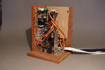

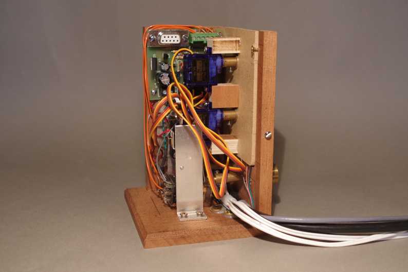
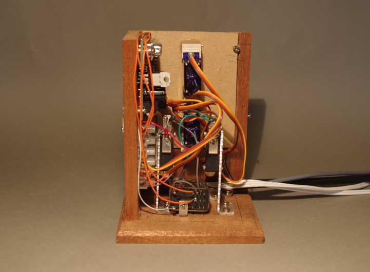
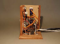 Here are a few photos which show the boxes. I wanted to make the instruments as small as possible, but perhaps overdid things -
 it’s very cramped inside, and it took me a while to figure out how to fit things in! The bell boxes are approximately 100mm in each dimension, whilst the instrument boxes are higher at about 125mm. At the top left is the MERG ‘Servo4’ circuit board, which controls the two servos in the instrument, and also in its partner. The two servos can be seen in the middle picture. At the bottom of the box is the relay which latches on/off to control the inputs to the Servo4 unit.

 At the front of the layout, the bell box and instrument box sit side-
by-side as shown in the picture, left. For the fiddle yards I have made a box which bolts to the back of the layout, shown right, with the bell box on top of the instrument.
The last little bit to do is to varnish the boxes - and the next problem of course is training the operators on the meaning of the various bell codes and the use of the plungers .......
 Much concentration required before the opening at Scaleforum........
Having successfully got the block bells operational at the Epsom and Ewell show, the block instruments were the next project.
There are many types of block instruments, which show the status of the line between two signal boxes -
There is a Tyer’s instrument in the Bluebell’s museum at Sheffield Park. The face of the instrument shows a signal post with two signal arms -
The ‘official’ instructions for use of these instruments are as follows. The letters ‘A’, ‘B’ and ‘C’ refer to three signal boxes in succession.
(a) Prior to the dispatch of a Train from “A” the Signalman there, provided he has received the Train Out of Section Signal from the previous Train and the Block Instrument is in its normal position, must call the attention of “B” on the Bell Key, and having obtained it must give the proper Is Line Clear Signal on the Bell Key. If the line be clear at “B” the signalman there must acknowledge the Signal on the Clear Key which will lower the white semaphore arm at “B” and the red arm at “A” to the Line Clear position.
(b) On the Train leaving “A” the Signalman there must send the Train Entering Section Signal on the Bell Key to “B”, who must acknowledge the signal on the Block Key which will raise the white arm at “B” and the red arm at “A” to the Line Blocked position.
(c ) “B” must then, provided he has received the Train Out of Section Signal for the previous Train and the Block Indicator is in its normal position, call the attention of “C”, and having obtained it must give the proper Is Line Clear Signal to “C”. If the line be clear “C” will give permission for the train to approach. As soon as the train has arrived at or passed “B” or been shunted clear of the main line at “B”, the Signalman there must give the Train Out of Section Signal to “A” on the Bell Key, which “A” must acknowledge.
 The photo shows one of the instruments. The Line Clear plunger is on the left, and the Line Blocked plunger on the right. The Bell Key is separate, on bell box, shown on previous pages.
In use on Plumpton, the only change is that when the fiddle yard operator asks ‘is line clear’, this indicates that the next train in the sequence is ready to go, but that the cassette is not yet electrically connected to the power. When the Plumpton box acknowledges ‘is line clear’, this indicates that the cassette can be connected, and when the fiddle yard operator sends ‘train entering section’ this indicates that the cassette is electrically connected. This doesn’t represent permission to drive onto the layout -
When a fiddle yard operator, having received a train, sends ‘train out of section’ this indicates that the cassette has been electrically disconnected.
There are two pairs of boxes, one between Plumpton and the Keymer Junction-
There have been several articles in the model railway press outlining methods of making block instruments, mostly using ammeters or voltmeters to provide the indications. I have chosen a rather different approach, using servos to operate the miniature arms on the Tyer’s instruments. This is possible with two position instruments, but possibly not when three positions are required.
The basic principle of my instruments is the use of a MERG (Model Electronics Railway Group) ‘Servo4’ driver. This circuit (supplied as a kit) is capable of driving four independent servos, each with its own setting of ‘on’, ‘off’, and speed of rotation in each direction. In each pair of my instruments there are four miniature arms, each with a servo, and hence one servo4 unit is sufficient for one pair of instruments. Once the servo on and off positions have been set it requires only a simple switch to toggle the servo between its two preset positions. (The servo positions and speeds are set using either a laptop with MERG software, or a MERG ‘Servoset2’ kit).
The ‘line clear’ plunger at the Plumpton box acts on a microswitch, which rings the bell on the fiddle yard box and also pulls in the relay. The relay is wired to latch (ie stay on) when the plunger is released. The relay then acts as the switch for two of the servos which move the miniature signals (the red one on the fiddle yard instrument, and the corresponding white one in the Plumpton box) to the off position. The ‘line blocked’ plunger rings the bell and un-
Similarly the two plungers in the fiddle yard box act on another relay, which operates the red arm at Plumpton and the white arm in the fiddle yard.
There is a relay in each of the boxes of the pair, but only one servo4 unit for each pair, which reside in the Plumpton boxes.
The power to the units is provided firstly by a 21v DC supply which drives the relays and the electromagnets which operate the bells, and secondly a separate regulated 12v DC supply for the servo4 unit. The pairs of boxes are connected using 25pin D connectors and cables.

 Here are a few photos which show the boxes. I wanted to make the instruments as small as possible, but perhaps overdid things -
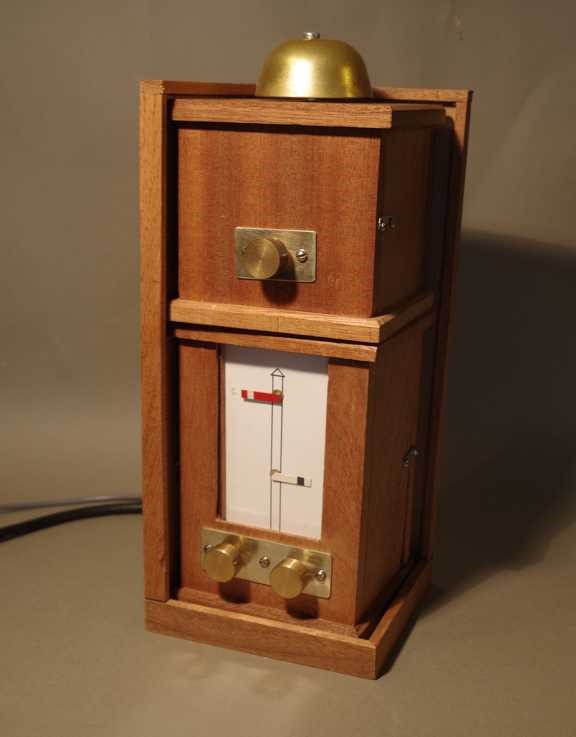
 At the front of the layout, the bell box and instrument box sit side-
The last little bit to do is to varnish the boxes -
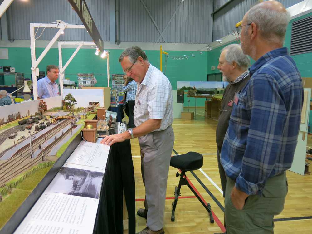 Much concentration required before the opening at Scaleforum........