

A selection of photos and drawings showing the development of the lever frames and locking frames:
 Left -
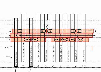
 an early version of a drawing (finished size) of the locking frame for the ground frame.
 Right -
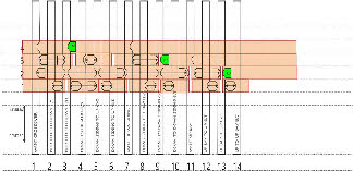
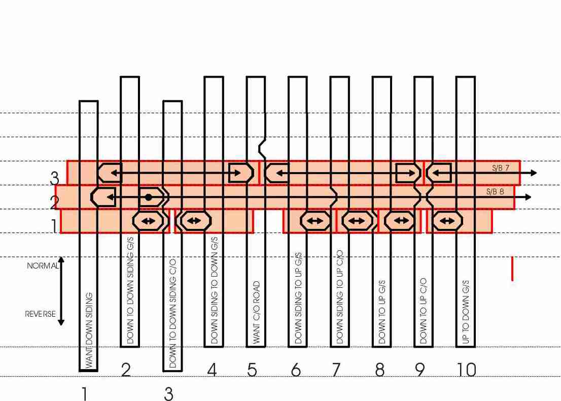
 the finished version after many iterations, including the addition of four more levers for the bay platform, and reversing all the levers (left to right) to reflect the fact that the model lever frame faces north, whereas the real one faced south.
 Left -
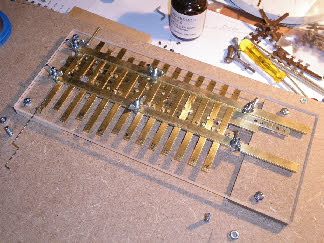
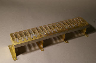
 the ground frame locking frame under construction. It is built on 6mm acrylic, because this is flat, and relatively low friction. The tappets and sliders are made from brass section, and part machined, part hand-filed to fit. The nibs on the tappets are 1/8” rod, force fitted into the tappets (rather than the conventional trapezoidal shaped nibs).
 Right -
 the finished lever frame for the ground-frame. An MSE kit, with a lot of additions and modifications to make it work satisfactorily. I’m happy with the end result, but this is a truly awful kit. The cast brass levers are the best bit.
 Left -
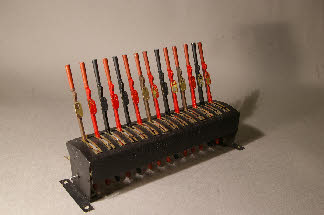
 the 18 lever frame for the signal cabin, made from a 14 lever MSE kit, reduced to 12 levers and cut in half, and with 6 levers from a 7-lever kit spliced into the middle. The brass rubbing strips either side of the lever slot are my own additions, to reduce slop in the levers. I have also added extra strengtheners to aid rigidity.
 Right -
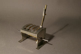
 a scratchbuilt frame with the first of the MSE cast levers added. This small frame controls the hand-operated, non-interlocked points in the good yard.
 Left -
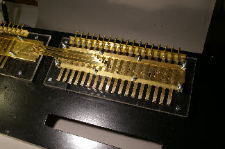
 the two complete locking frames fitted to the control panel base, and awaiting the fitting of the lever frames. The three connecting bars between the two frames represent the release locks for the ground frame. In reality the levers in the signal cabin frame (the right hand one) operate bolt locks on the switch blades - rather difficult to replicate at 4mm:ft.
 Right -
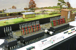
 the final control panel, at a much later stage, with the three lever frames (left - the goods yard points; centre - the ground frame; right - the signal cabin frame). The electrical controls are also in view - push buttons for electromagnetic uncouplers in the middle, and radio button switches for section control to left and right. The block instruments for the Plumpton - Cooksbridge block are in view on the right. The Plumpton - Keymer Junction instruments are out of view on the left.
 Left -
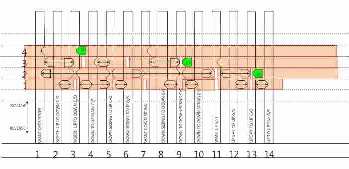 Right -
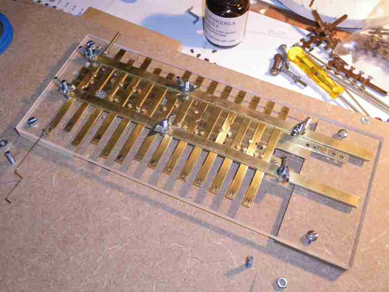 Left -
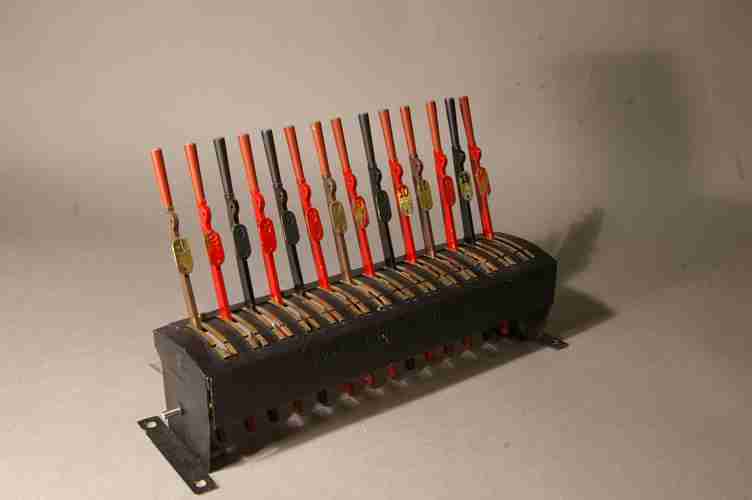 Right -
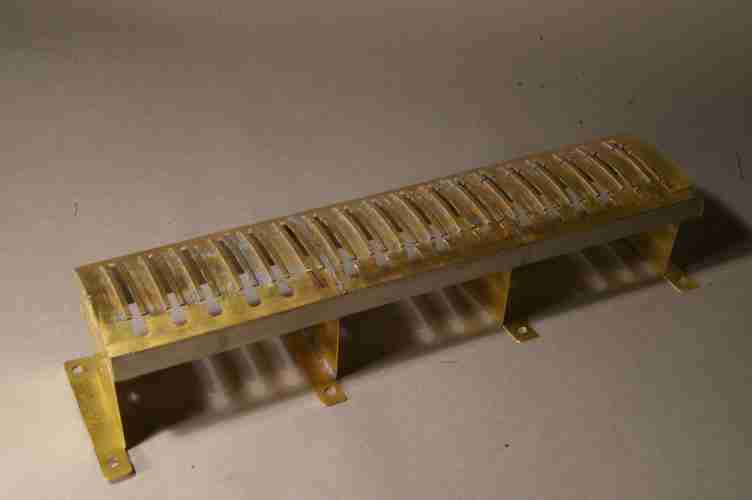 Left -
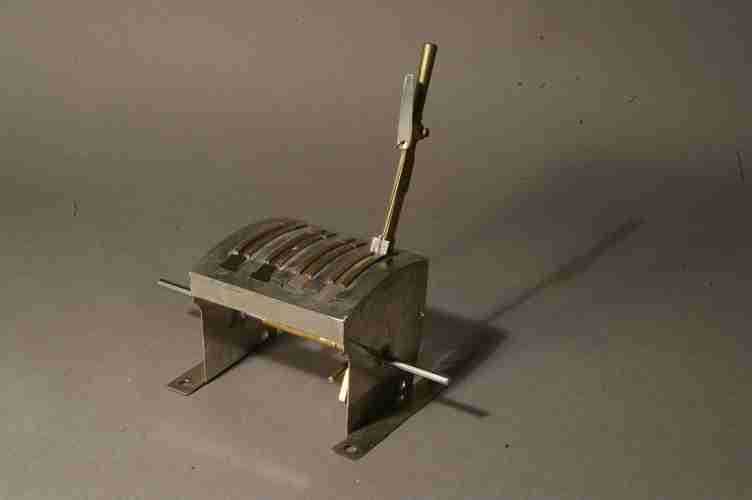 Right -
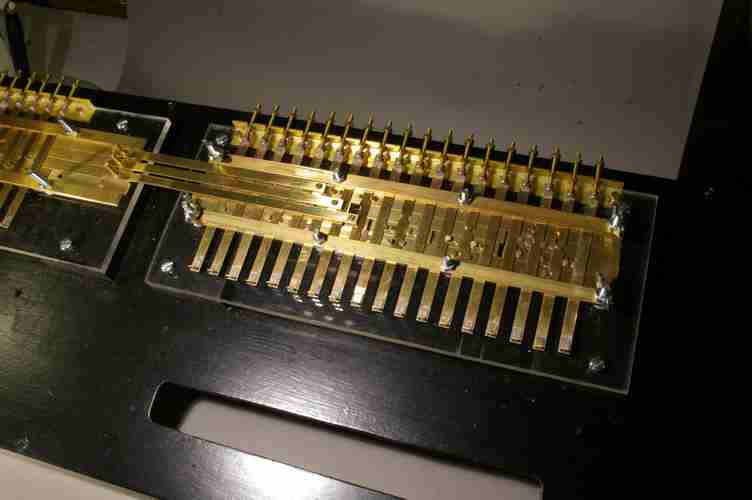 Left -
 Right -