


Last updated Jan 2026
1st June 2012. First day of retirement, so off to the Bluebell Railway to do some more work in the Carriage and Wagon Department, helping restore a wooden carriage from 1890 – one of William Stroudley’s 4-wheel 5 compartment thirds.
On the model railway front, ‘Brighton Road’ is more-or-less complete, so is retirement a good time to start a new layout? What could we (myself and son Chris) build? Something smaller than Brighton Road – perhaps something local? It would have to be LBSCR, around 1900-1914, at a scale of 4mm:1ft (P4) just because of the rolling stock and locos we have. It would be good to build a smallish layout for exhibition, which only requires, say, three or four people to operate for a week-end, but would also fit into my garage.
The Mid-Sussex Group’s layout ‘Pulborough’ was as near as we could get to a full-scale model of a prototype, and was interesting to build and very interesting to operate, whereas ‘Brighton Road’ is fictitious, and only loosely based on Brighton prototypes. Pulborough looks like the real thing, and although Brighton Road looks good, and is very challenging to operate because of its complexity, it doesn’t have the same attachment to reality as Pulborough. This leads us down the road of building a layout closely based on a real location, at a reasonably defined time period. Is there a suitable location? The idea of building something local which can be easily visited has some appeal.
The ‘Brighton’ has very few termini, and most of these are much too large to model – Brighton, Littlehampton, Bognor, Portsmouth etc – or too small, such the Devil’s Dyke branch. We want to be able to exhibit the layout, but also to be able to set it up in my garage, which is a fairly generous 20ft, but a bit tight for an end-to-end layout. Two fiddle yards at a minimum of 4ft each would only leave 12ft for the scenic bit – not enough. However, my good friend Martin Nield came up with the suggestion of building an end-to-end layout, but making sure that it could be run as a terminus in the garage. This would need only one fiddle yard, and leave 16ft for the scenic section, which might be do-able. For high days and holidays, the garage doors can be opened, the second fiddle yard attached, and the layout could be operated end-to-end.
So here is the specification for the layout:
1st June 2012. First day of retirement, so off to the Bluebell Railway to do some more work in the Carriage and Wagon Department, helping restore a wooden carriage from 1890 – one of William Stroudley’s 4-
On the model railway front, ‘Brighton Road’ is more-
The Mid-
The ‘Brighton’ has very few termini, and most of these are much too large to model – Brighton, Littlehampton, Bognor, Portsmouth etc – or too small, such the Devil’s Dyke branch. We want to be able to exhibit the layout, but also to be able to set it up in my garage, which is a fairly generous 20ft, but a bit tight for an end-
So here is the specification for the layout:
· P4 standard at 4mm:1ft
· LBSCR around 1900-1914
· Based as far as possible on a real location, preferably local
· Through station, not terminus
· Transportable and designed for exhibition
· Able to be set up and operated in the garage
· 20ft maximum length with one fiddle yard attached, and 24-25ft with two
· Able to be operated by two people, but with enough interest to keep four occupied
· Buildable by two people (myself and son Chris) to an exhibitable state within two years
· Realistic in the sense of countryside with a railway through it, rather than a railway with some scenery bolted on
 My local station is Plumpton, on the Keymer Junction to Lewes line in East Sussex, which eventually goes eastward to Newhaven Harbour, Seaford, Eastbourne and
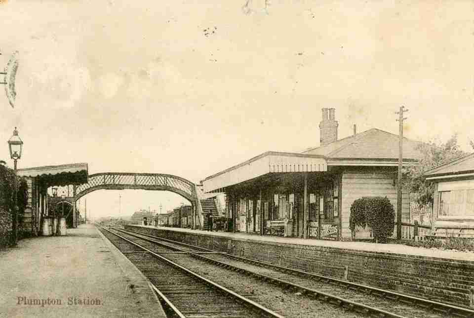
 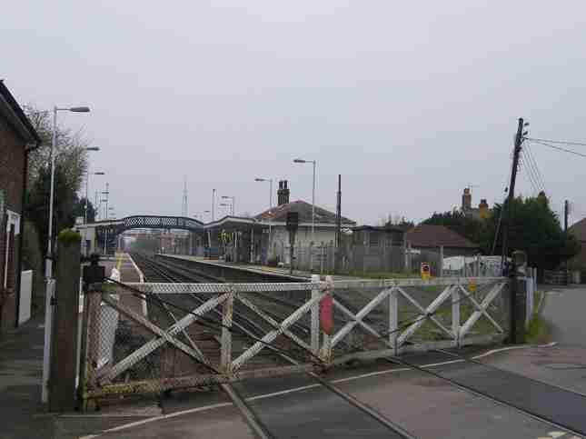 Hastings. The station is now a shadow of its former self – just double track secondary main line. However, it still retains some of its original features – the up waiting room and station building dating from 1863, the footbridge from about the same date, and the signal cabin from 1891, plus capstan operated level crossing gates (although not the original gates). The mechanical signals have long-
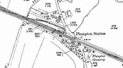 My copy of the Middleton Press book ‘Haywards Heath to Seaford’ contains a map of Plumpton dated 1909, which shows a goods yard with three sidings and a side & end loading dock, plus another siding east of the station on the up line. The map also seems to show two platform buildings which no longer exist, although the accompanying photographs do not make clear what these buildings might be. Must find some more photographs!
Plumpton would have seen quite a few passenger trains each day, some stopping, some not, not least because it is on the route to Newhaven Harbour, and the Cross-
A promising start for some more detailed research, but can Plumpton be accommodated in 16ft of model?
The first step is to acquire maps for the area around 1910, to show a little more than the Middleton Press book. www.old-
These maps show various things, including positions of running signals, but most interestingly, that the siding on the up side, east of the station is about 1250ft long, and the head shunt to the goods yard on the down side is a little shorter at about 1000ft. These sidings (lay-
However, modelling the entire station, including these two lay-
I’ve not previously used Templot, but it’s the obvious choice for a new layout, so it’s time to shell out for a copy – except that logging onto the web-
One key component which I would like to include is a fully mechanically interlocked lever frame – something I’ve not attempted before, and which will certainly need some research – what to do and how to do it. The Signalling Record
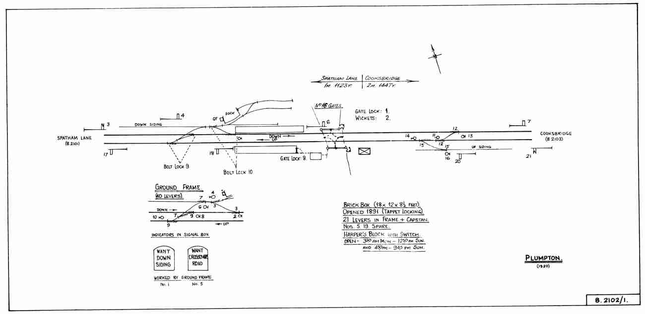 Society’s Book on LBSCR signal boxes shows the Plumpton Signalling Diagram for 1920, with the track plan and signalling unchanged from 1910 (see diagram on left). This shows that in addition to the main signal box to the east of the station, adjacent to the level crossing, there was also a ground frame in the goods yard, controlling signals and turnouts for the yard entry. I presume this is because the distance from the box to these turnouts was more than 250 yards, which the Brighton regarded as the limit for safe operation of turnouts. The box and the ground frame were linked by levers on the ground frame to request operation of the crossovers, and levers in the box which released bolt locks on the turnouts.
The diagram very helpfully shows all the lever numbers, but doesn’t have any indication of how they were interlocked. Having spent a few days during the month thinking about this, and making numerous drafts of locking tables, and diagrams, I’m getting somewhere, but I’m not sure I’ve got it right.