


September 2012. Lots more activity on the trackwork. Most of the sleepers are now in place on the four boards, and Chris has made lots of progress on soldering the rails in place.
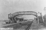
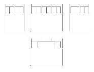
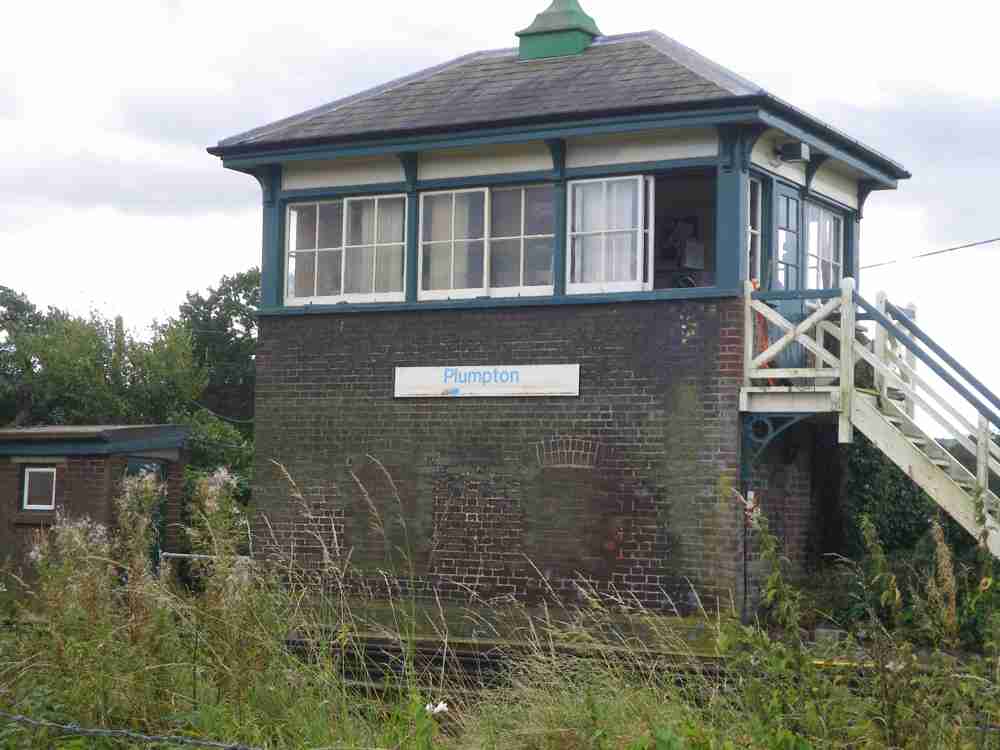
 Another walk to the station and I have been able to photograph the signal box, up waiting room and footbridge. I have also taken the basic measurements of the waiting room, and prepared a drawing.
 I think it’s well-
worth preparing scale drawings of buildings, to make sure everything looks right before starting building work. Transferring measurements direct to plasticard may seem quicker, but in the long run I think might lead to more mistakes (well – it has in the past for me!).
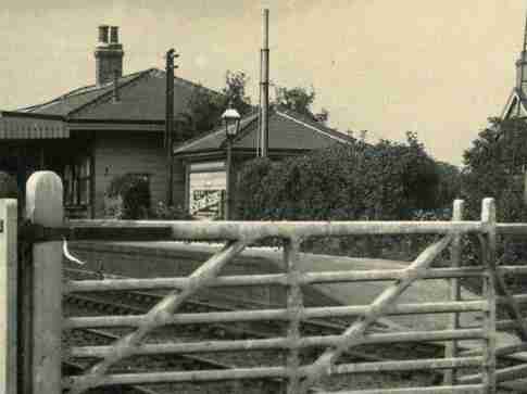
As part of the local Jubilee celebrations one of our local historians has published a little booklet of historic postcards of Plumpton, including a couple of very interesting views from around 1910, giving just slightly better views of the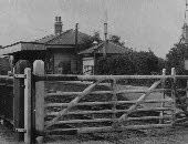 station, and the two mysterious buildings which no longer exist. One of them looks very much like a signal box, and could have been the original box prior to the current (1891) box – but why is it still there in 1910 – and even in early Southern days? The other building is just tantalisingly out of view. Most of the shots are taken from the level crossing end (east end) of the station. A view from the western end would be invaluable.
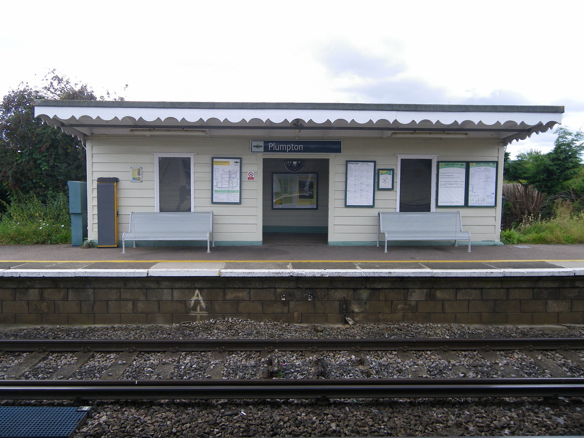
 I’m a fairly frequent visitor to our village hall, and there are about a dozen historic pictures of Plumpton in the entrance hallway. I’ve looked at these a few times, but clearly hadn’t been paying attention. Another visit last night, and a casual look at the pictures – and there it is – a shot from the west end of the station. This shows reasonably clearly that the missing building at the west end is in fact a close but not identical version of the up (still existing) waiting room.
The size of the building is confirmed by the footprint on the plans I have. I can’t quite see enough to confirm the positions of the windows and doors, but enough to make an intelligent guess.
At Scaleforum I made contact with Lens of Sutton, and their catalogue shows 14 pictures of Plumpton, although none dated. The only answer is to order the lot – a few weeks to wait to see what they show.
I’ve now got most of the components to make the locking frames. The main box will have 18 levers, and the ground frame 14. The main box has three levers which release point locks (ie physically prevent the blades from moving) on the cross-overs controlled by the ground frame. This would be very difficult to implement in model form so I’ve opted to mimic the effect by adding additional locking bars between the two frames so that the levers on the ground frame can’t be moved until the locks are released.
I already have one of the MSE 14 lever frames, and although I have been advised against using these (they are badly designed and drawn) I feel I can’t simply throw away this investment and start again. The downside is that I have to buy another 14 lever frame, plus a 7 lever frame. Will I regret this? I also need to decide how to operate the four locally operated turnouts in the yard which are not interlocked with anything.
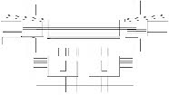
At Scaleforum I have just bought a very useful book ‘Signalling and Lever Frames’ by Jeff Geary on signalling and interlocking, which includes a programme called Trax. This is very simple to use to create a signal and track plan together with a locking table, and then to operate the lever frames to check that the interlocking does what it should. It’s taken just a few hours to create a drawing of the proposed layout, and the locking table – and it seems to do what it should, so I think I’m ready to start cutting metal!
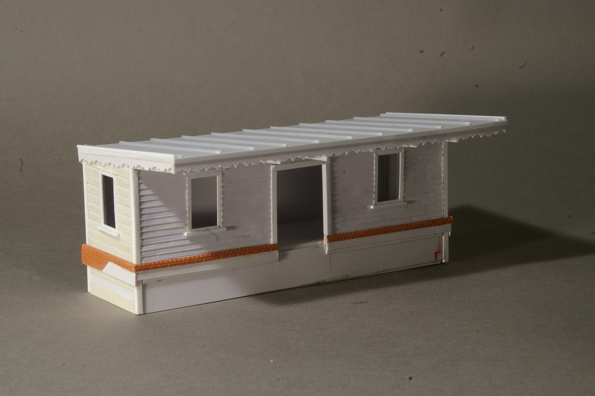
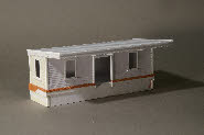 Building the up waiting room has not taken long, although we haven’t yet made the windows. Working from my drawing it’s only taken a few days to cut the main components and assemble it. We’ll put it to one side for painting at a later date when the other buildings are finished.
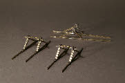 As a break from trackwork, I’ve also made the main components of the three buffer stops -
 something else to put aside for painting at a later date.
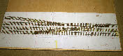
October 2012. Trackwork is proceeding very quickly – all the sleepers are in place, and most of the rail is in place on two of the boards. Making the crossing V’s and switch rails for the turnouts takes a bit of time, but there are only 15 to make, and we’re about halfway through.
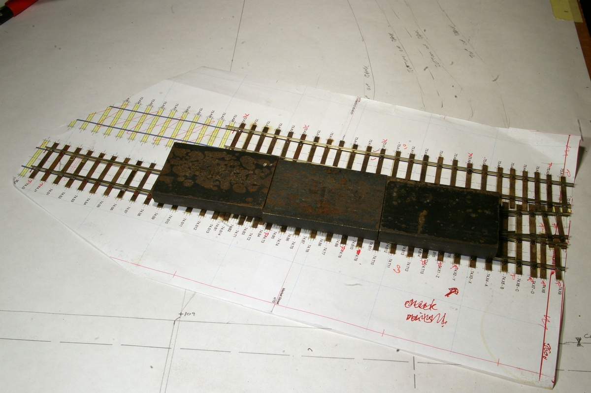
 The functional chairs are being glued to the sleepers using a strong plastic adhesive – Butanone, or Plasweld. This dissolves the plastic sufficiently, so that with the aid of some heavy-
ish weights on top, the base of the chair ‘melts’ into the grain of the wooden sleeper, and makes a reasonably strong mechanical bond. The trackwork for Brighton Road was built like this, and has given very little trouble. If the track gauge needs adjusting, the bond can be broken with a scalpel blade, and subsequently rejoined.
If a stronger bond is needed, then a dab of Polypipe cement on the sleeper (and allowed to dry) before gluing down the chair, will provide an almost unbreakable joint.
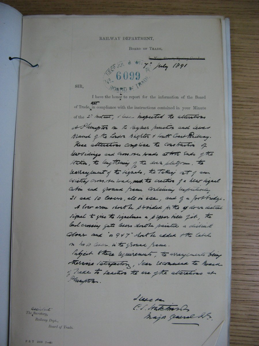
I’m still a bit puzzled about one aspect of locking in the ground frame. From the up line there are two potential crossover routes – either to the down line, or into the yard, but only one ground signal. Did this cover both routes, or was only one permitted? I suspect the former, but I don’t know.
 However, Ian White has turned up a couple of documents at Kew PRO relating to Plumpton. One of these is the Inspector’s report from the track modifications and re-
signalling from 1891. By an amazing bit of serendipity this report recommends a change to the labelling of one of the ground frame levers, clearly indicating that one ground signal covers both possible routes.
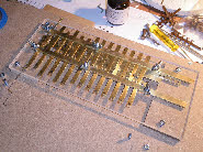 Having sorted out this final bit of detail, progress on the ground frame locking frame has been very fast. With the aid of a milling machine and a few hand tools it’s only taken me a few days to get the basics done. It needs a lot of fine tuning to make it work smoothly, and I have still to make the associated lever frame.
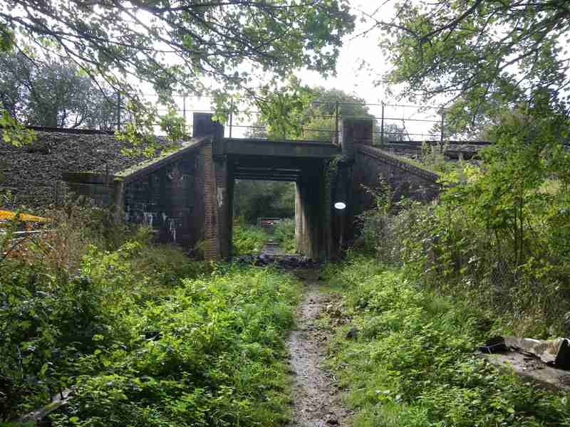
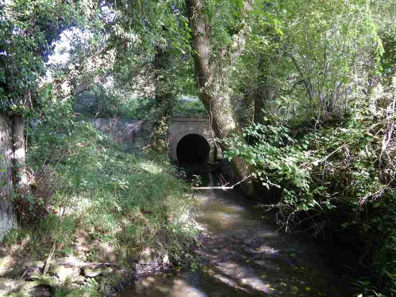
We’ve started to think about the scenic elements of the layout, and what to use as ‘book-ends’. There aren’t any road over rail bridges round here so I’ll have to find something else. To the west there is a rail over-bridge over an accommodation crossing, and to the east there is a stream crossing under the railway. Although both of these are too far away to be within our 16ft, they’re nice features so worth moving them inwards to be included on the layout.
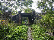
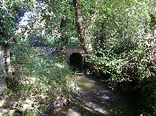 A short walk and a few photographs later, and we have enough information to draw these two crossings. As a break from making track work Chris has made the wing-
walls for the accommodation crossing.
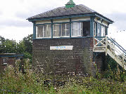
 I’ve finished measuring and drawing the signal box, but I haven’t quite decided how to make it – especially how to make it robust with so much of the top half being window.
 Another walk to the station and I have been able to photograph the signal box, up waiting room and footbridge. I have also taken the basic measurements of the waiting room, and prepared a drawing.
 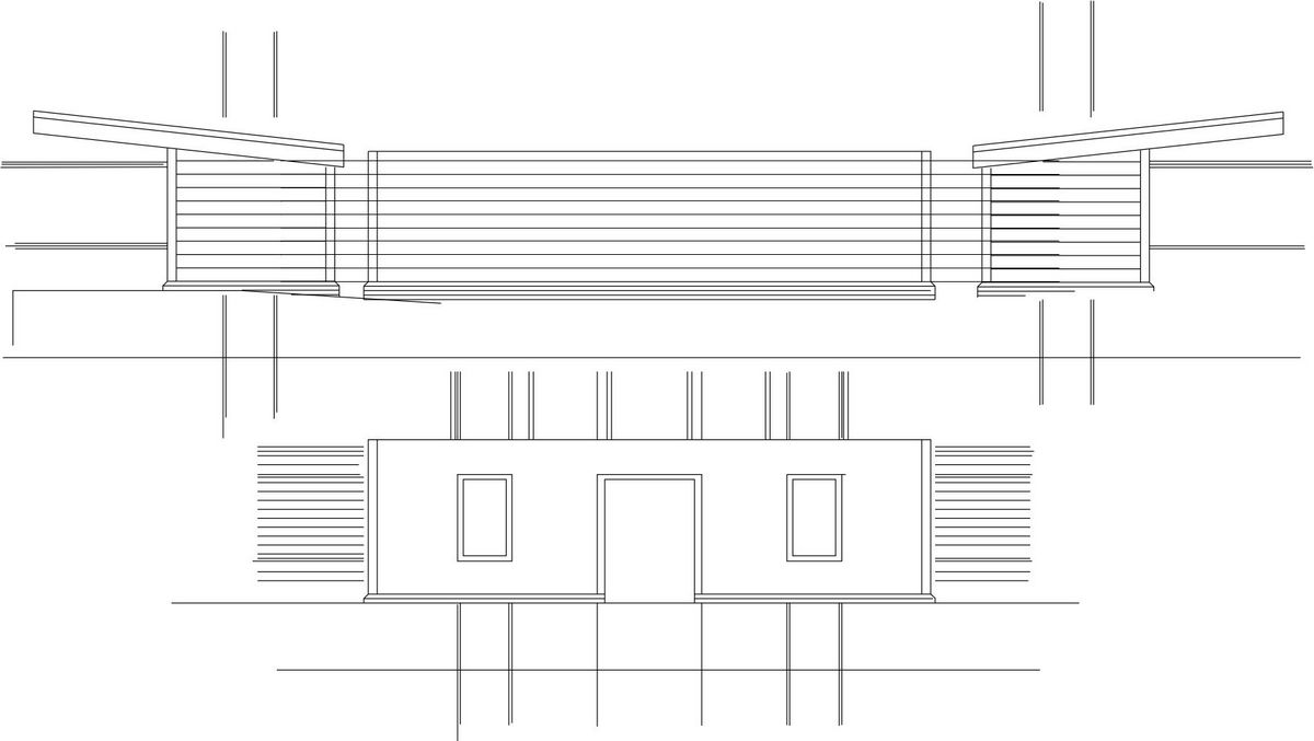 I think it’s well-
As part of the local Jubilee celebrations one of our local historians has published a little booklet of historic postcards of Plumpton, including a couple of very interesting views from around 1910, giving just slightly better views of the
 station, and the two mysterious buildings which no longer exist. One of them looks very much like a signal box, and could have been the original box prior to the current (1891) box – but why is it still there in 1910 – and even in early Southern days? The other building is just tantalisingly out of view. Most of the shots are taken from the level crossing end (east end) of the station. A view from the western end would be invaluable.
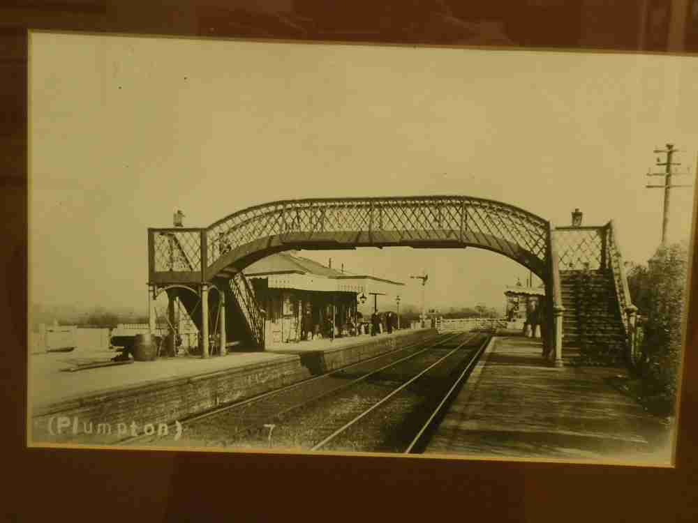 I’m a fairly frequent visitor to our village hall, and there are about a dozen historic pictures of Plumpton in the entrance hallway. I’ve looked at these a few times, but clearly hadn’t been paying attention. Another visit last night, and a casual look at the pictures – and there it is – a shot from the west end of the station. This shows reasonably clearly that the missing building at the west end is in fact a close but not identical version of the up (still existing) waiting room.
 The size of the building is confirmed by the footprint on the plans I have. I can’t quite see enough to confirm the positions of the windows and doors, but enough to make an intelligent guess.
At Scaleforum I made contact with Lens of Sutton, and their catalogue shows 14 pictures of Plumpton, although none dated. The only answer is to order the lot – a few weeks to wait to see what they show.
I’ve now got most of the components to make the locking frames. The main box will have 18 levers, and the ground frame 14. The main box has three levers which release point locks (ie physically prevent the blades from moving) on the cross-
I already have one of the MSE 14 lever frames, and although I have been advised against using these (they are badly designed and drawn) I feel I can’t simply throw away this investment and start again. The downside is that I have to buy another 14 lever frame, plus a 7 lever frame. Will I regret this? I also need to decide how to operate the four locally operated turnouts in the yard which are not interlocked with anything.
At Scaleforum I have just bought a very useful book ‘Signalling and Lever Frames’ by Jeff Geary on signalling and interlocking, which includes a programme called Trax. This is very simple to use to create a signal and track plan together with a locking table, and then to operate the lever frames to check that the interlocking does what it should. It’s taken just a few hours to create a drawing of the proposed layout, and the locking table – and it seems to do what it should, so I think I’m ready to start cutting metal!
 Building the up waiting room has not taken long, although we haven’t yet made the windows. Working from my drawing it’s only taken a few days to cut the main components and assemble it. We’ll put it to one side for painting at a later date when the other buildings are finished.
 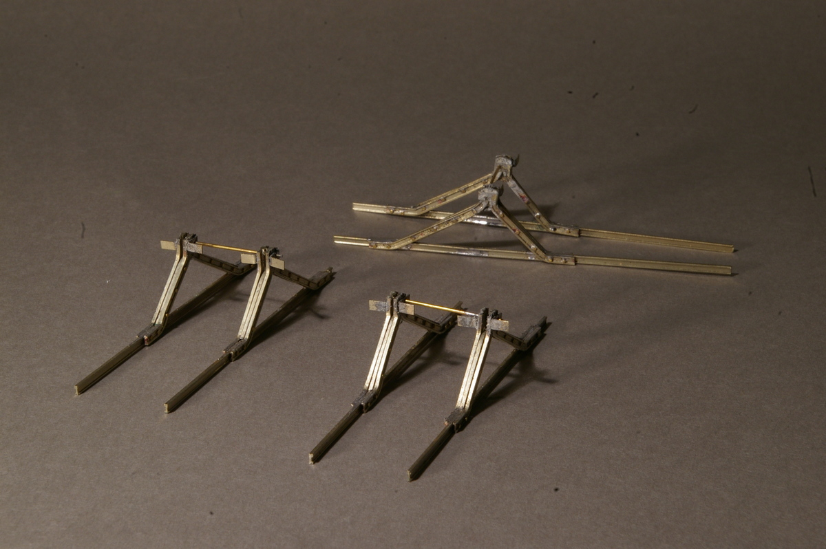 As a break from trackwork, I’ve also made the main components of the three buffer stops -
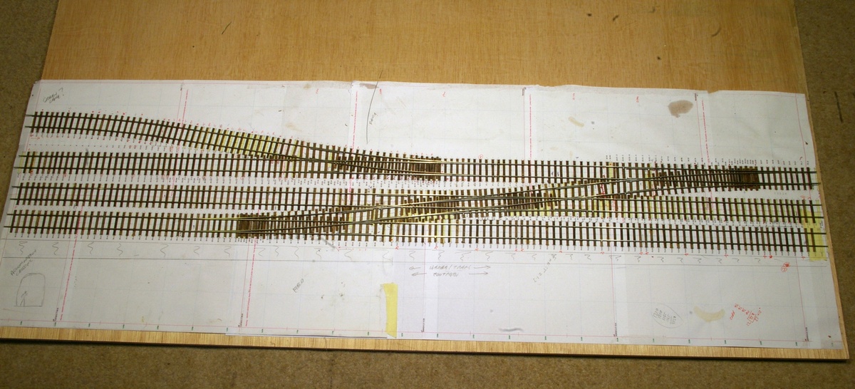
October 2012. Trackwork is proceeding very quickly – all the sleepers are in place, and most of the rail is in place on two of the boards. Making the crossing V’s and switch rails for the turnouts takes a bit of time, but there are only 15 to make, and we’re about halfway through.
 The functional chairs are being glued to the sleepers using a strong plastic adhesive – Butanone, or Plasweld. This dissolves the plastic sufficiently, so that with the aid of some heavy-
If a stronger bond is needed, then a dab of Polypipe cement on the sleeper (and allowed to dry) before gluing down the chair, will provide an almost unbreakable joint.
I’m still a bit puzzled about one aspect of locking in the ground frame. From the up line there are two potential crossover routes – either to the down line, or into the yard, but only one ground signal. Did this cover both routes, or was only one permitted? I suspect the former, but I don’t know.
 However, Ian White has turned up a couple of documents at Kew PRO relating to Plumpton. One of these is the Inspector’s report from the track modifications and re-
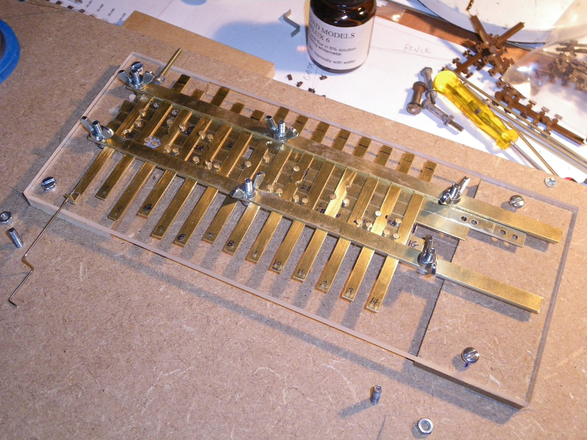 Having sorted out this final bit of detail, progress on the ground frame locking frame has been very fast. With the aid of a milling machine and a few hand tools it’s only taken me a few days to get the basics done. It needs a lot of fine tuning to make it work smoothly, and I have still to make the associated lever frame.
We’ve started to think about the scenic elements of the layout, and what to use as ‘book-
 A short walk and a few photographs later, and we have enough information to draw these two crossings. As a break from making track work Chris has made the wing-
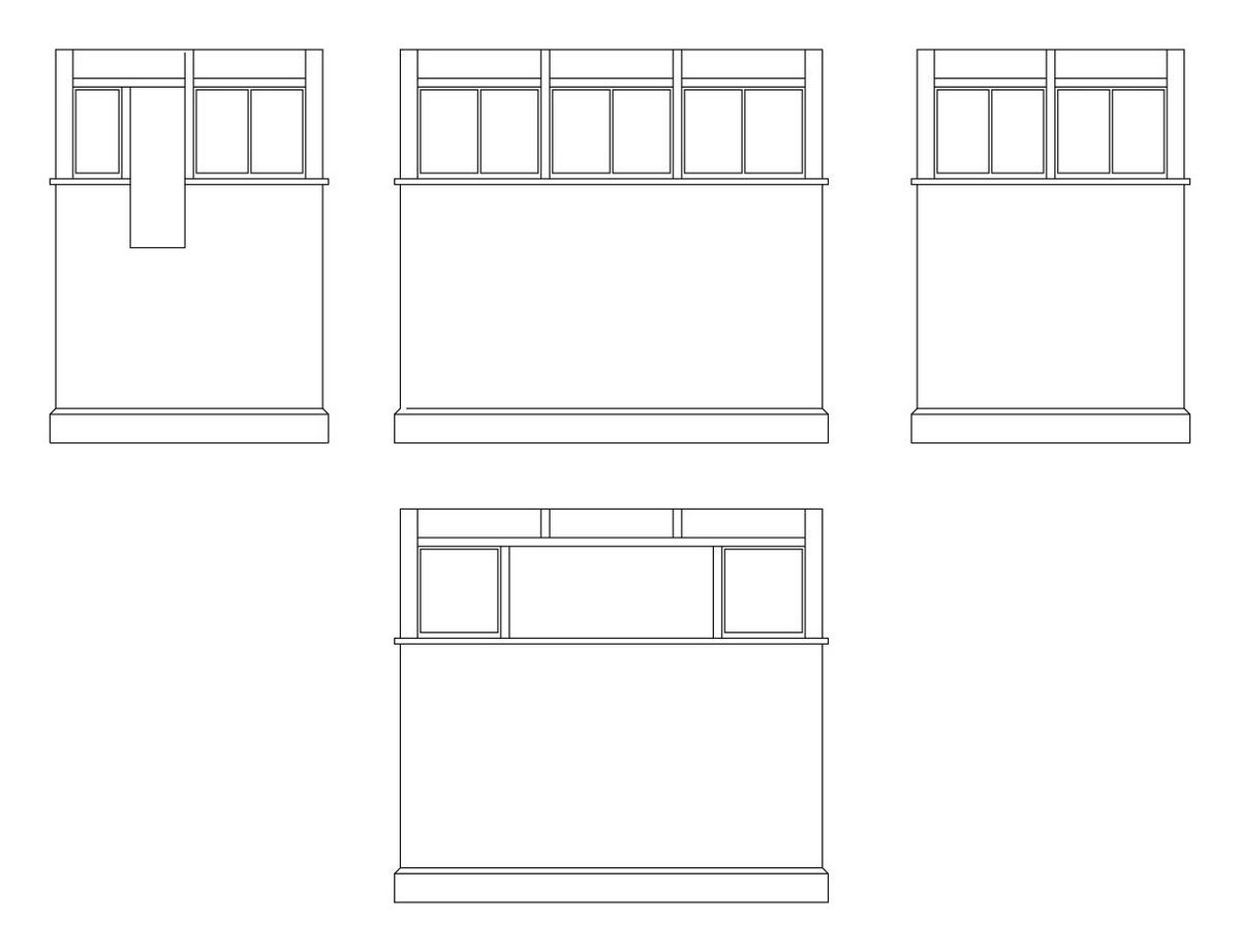 I’ve finished measuring and drawing the signal box, but I haven’t quite decided how to make it – especially how to make it robust with so much of the top half being window.