
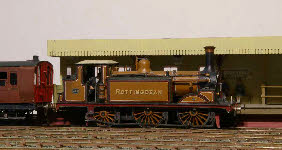


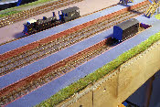
December 2013. Another milestone has been reached - we have erected all four boards together for the first time, and run a loco all over it. It’s a bit of a squeeze getting 16ft of layout into my work-room but it just fits.
 The London end of the layout has now been more or less completed, although there is still plenty of detail that can be added in the future, so we’ve transferred attention to the ‘Lewes’ end. There is a culverted stream some distance east of Plumpton, which makes quite an interesting feature, so we’ve moved it westward to fit it onto our model. The culvert is a large brick-
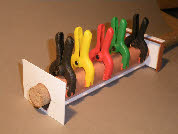
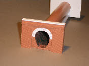
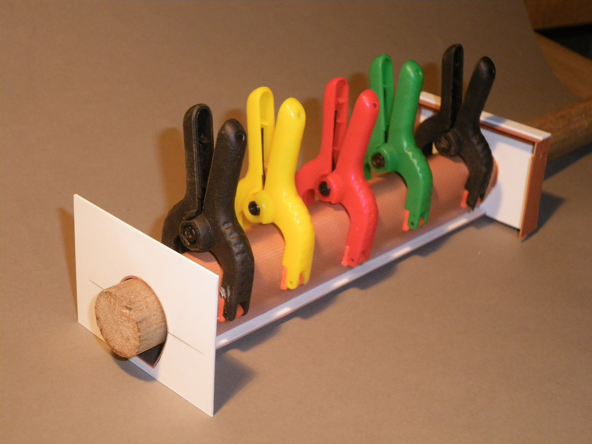
egg construction about 7’6” in height, with a substantial brick headwall at either end. The photos show how the culvert was made - Slaters brick plasticard wrapped around an old broom handle, and clamped in place while being glued to a flat base. The invert of the culvert should of course be radiused rather than flat, but since the water surface will be flattish, the absence of a semi-circular invert will not be evident. The brick arch over the pipe in the second photo is made of individual rectangles of plastic.

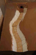
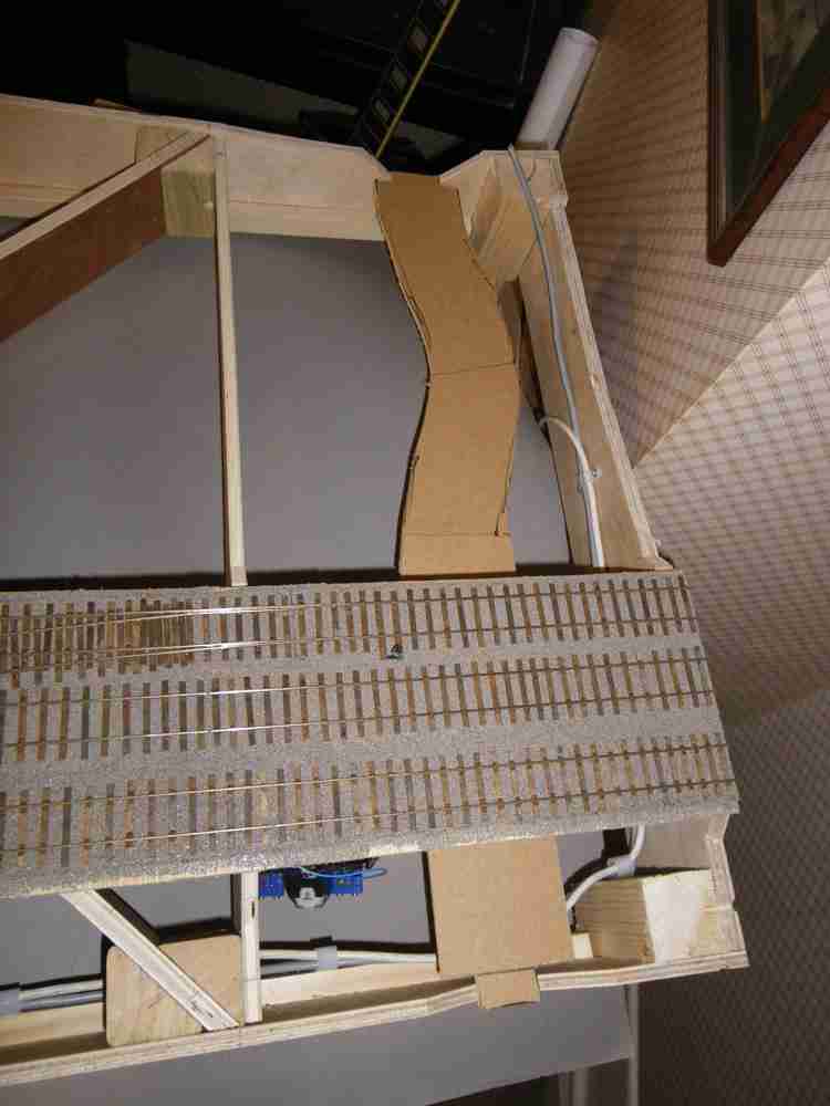
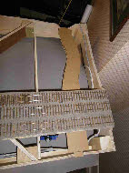 I’ve also started to build the base of the stream, as shown in the photos, which show the open frame base-
boards with the stream bed in place. The open section of the base-boards will be covered with 3mm MDF, and I’ll make the banks of the stream out of card, before finally shaping the stream with several coats of artex.
With a bit of experimentation I have sorted out a way of making the platforms. Unfortunately my camera has broken, so no pictures are available. The platform faces have been put together from Slater’s plasticard. We’ve sprayed these with Halford’s red acrylic primer to give a basic colour, and a sound surface for applying subsequent coats. For the mortar we have painted on a thinned-down coat of Humbrol no 103, and allowing a about a minute or so for the paint to dry just a bit, we’ve then wiped off most of it, leaving paint in the mortar indentations. Finally, when this has dried completely, we’ve dry-brushed on the finish colour, using several brick-colour paints to give a little variation in the final colouring.
The platform surfaces are made from 1mm ply, with 400 grit wet and dry paper glued on top. Tarmac is grey not black, so we’ve given it a light spray with grey acrylic primer. When finished we’ll re-spray with an airbrush and add a light touch of weathering powder to give a little variation in colour.
Joining the ply top and the plastic faces presented a bit of a challenge. I eventually hit on the idea of holding the top and faces together upside-down, and running a seam of glue from a glue gun along the join. Structural stability is provided by plasticard supports fixed across the width of the platform between the platform faces, every 40-50 mm.
With all the base-boards erected, we can now run engines all over the layout, and test the ground signals and A-J magnets. Sadly a few things don’t work. A bit of work to track down the problem, and it’s clear that some of my soldering is not what it should be. However, half-a-dozen or so dry joints is not too bad, considering how many hundreds of joints there must be on the layout.
 January 2014. Things have moved forward quite a lot during January, although perhaps not a lot to write about. The main thing is that all the platforms are finished and fitted, needing just weathering to complete. This has transformed the layout.
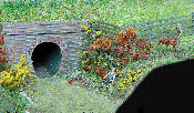
 The culvert has also been finished, painted and fixed in place, allowing the rest of the open frame base-
board to be covered in, and the basic profile of the stream bed completed, shown in the photo left.
 In terms of finishing the ‘topography’ of the layout (ie the basic shapes of the landform) we need to finish the road, and sort out the size and position of the level crossing gates. The road crosses a baseboard joint at a very shallow angle, and a visible join along the length of the road would look pretty terrible, so we’ve decided to make the road as a removable section, to be fitted across the base-
board joint. This is not so easy since the road is not flat - it dips towards the goods yard entrance and rises up to rail level at the level crossing. I think we’ve solved this by gluing together two lengths of 3mm MDF and clamping in place while the glue dries. Hopefully it will retain its curved profile when the clamps are removed. The photo shows the gap in the base-boards, and the section of road which fits in - held in place by two 3mm bolts.
February 2014. All the base-boards are now completed in terms of the basic topography - the railway embankments are finished, the broad shape of the stream is done, and the road is in place. The last of the fencing has been made and painted, and awaits grass on the embankment before it can be fixed permanently in place.
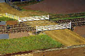
I’ve also made the level crossing gates. These are different from the current ‘modern’ gates, but fortunately we have a good photo of the original gates. Rather than butt joints at the corners of the gates, (not very strong) I have made the main components of the gates from thin strips of Evergreen plastic, laminated together, and interleaved at the corners, creating a pseudo mortise and tenon joint.
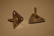
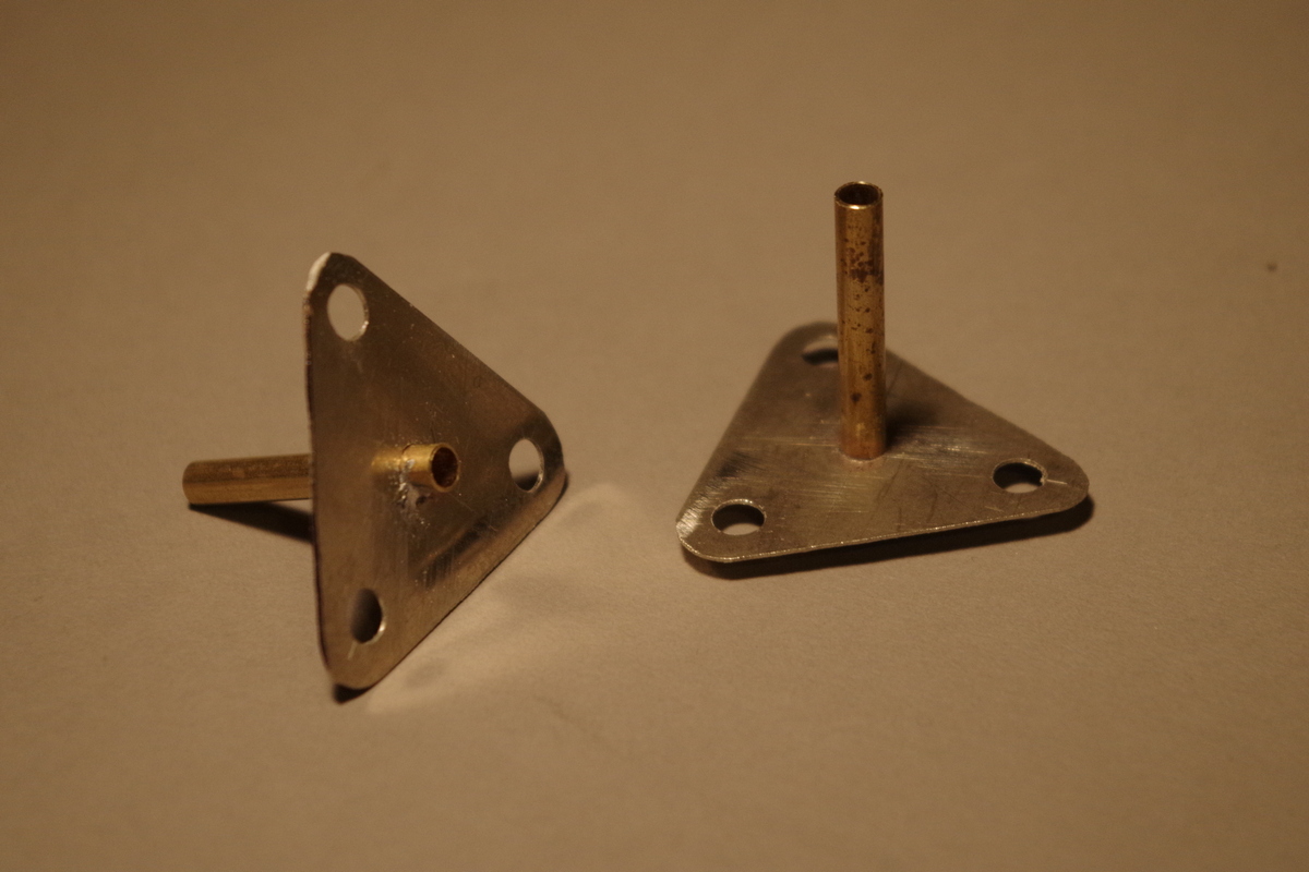
 A problem I had with gates on Brighton Road, is making sure that the gate post is absolutely plumb, so that whether the gate is open or closed, it is parallel with the ground. Another problem with level crossing gates is making sure that when open or closed, they are the correct distance apart (ie without a huge gap between the gates). I’ve solved this by making base plates, as shown in the photo, left. These fit into oversize holes in the baseboard, so can be adjusted to give the right spacing for the gates, and also, by packing under one or other of the corners of the triangle, can be finely adjusted, so that the gate pivot is truly plumb as shown in the photo, above right.
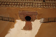
 We’ve been wondering how to give the stream bed north of the culvert a bit more realistic shape, and while rooting round in my box of scenic bits and pieces, came across an unopened packet of ‘Das’ modelling clay, which must be at least 30 years old. Amazingly, it is still usable, so has been applied to the stream bed and banks to give the necessary shape. The entry into the culvert has been completed with water and other autumnal scenic detail added.
I’ve at last made a start on the signal box.
 The London end of the layout has now been more or less completed, although there is still plenty of detail that can be added in the future, so we’ve transferred attention to the ‘Lewes’ end. There is a culverted stream some distance east of Plumpton, which makes quite an interesting feature, so we’ve moved it westward to fit it onto our model. The culvert is a large brick-
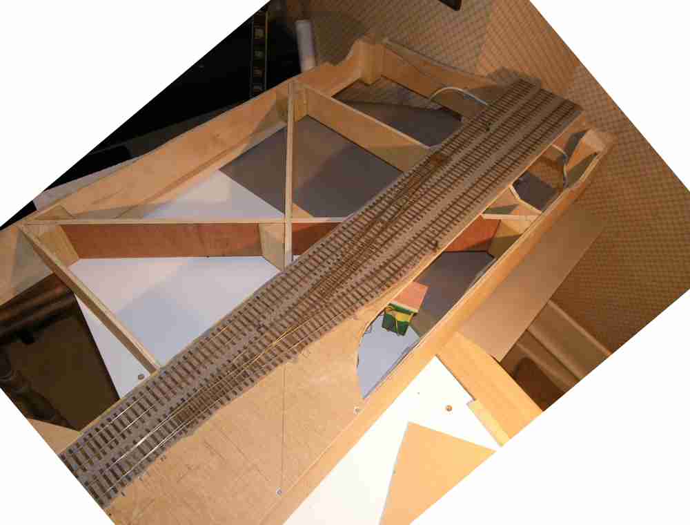
 I’ve also started to build the base of the stream, as shown in the photos, which show the open frame base-
With a bit of experimentation I have sorted out a way of making the platforms. Unfortunately my camera has broken, so no pictures are available. The platform faces have been put together from Slater’s plasticard. We’ve sprayed these with Halford’s red acrylic primer to give a basic colour, and a sound surface for applying subsequent coats. For the mortar we have painted on a thinned-
The platform surfaces are made from 1mm ply, with 400 grit wet and dry paper glued on top. Tarmac is grey not black, so we’ve given it a light spray with grey acrylic primer. When finished we’ll re-
Joining the ply top and the plastic faces presented a bit of a challenge. I eventually hit on the idea of holding the top and faces together upside-
With all the base-
 January 2014. Things have moved forward quite a lot during January, although perhaps not a lot to write about. The main thing is that all the platforms are finished and fitted, needing just weathering to complete. This has transformed the layout.
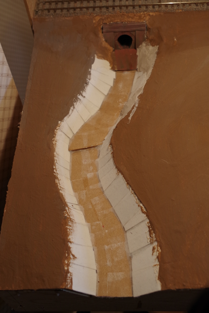 The culvert has also been finished, painted and fixed in place, allowing the rest of the open frame base-
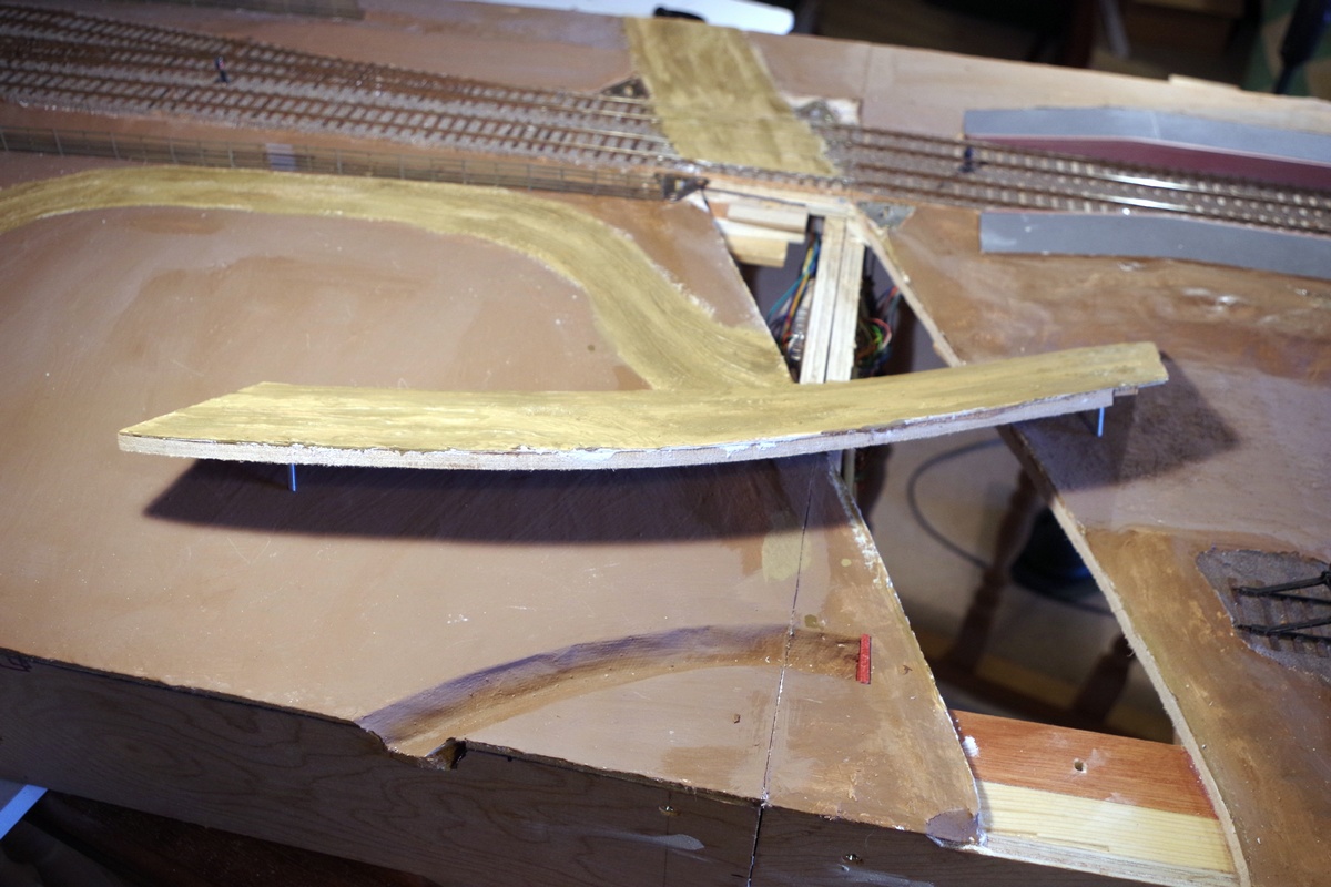 In terms of finishing the ‘topography’ of the layout (ie the basic shapes of the landform) we need to finish the road, and sort out the size and position of the level crossing gates. The road crosses a baseboard joint at a very shallow angle, and a visible join along the length of the road would look pretty terrible, so we’ve decided to make the road as a removable section, to be fitted across the base-
February 2014. All the base-
I’ve also made the level crossing gates. These are different from the current ‘modern’ gates, but fortunately we have a good photo of the original gates. Rather than butt joints at the corners of the gates, (not very strong) I have made the main components of the gates from thin strips of Evergreen plastic, laminated together, and interleaved at the corners, creating a pseudo mortise and tenon joint.
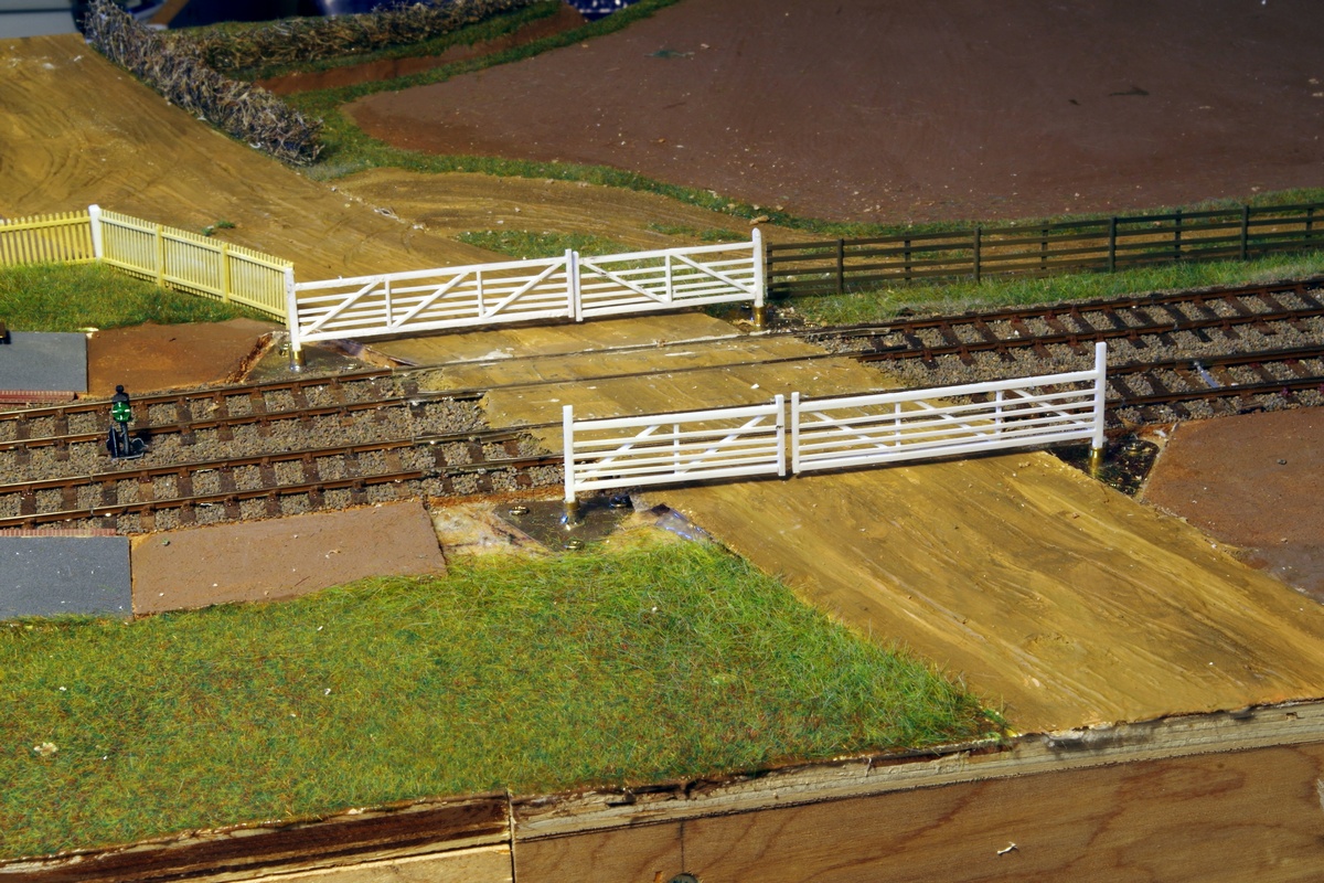 A problem I had with gates on Brighton Road, is making sure that the gate post is absolutely plumb, so that whether the gate is open or closed, it is parallel with the ground. Another problem with level crossing gates is making sure that when open or closed, they are the correct distance apart (ie without a huge gap between the gates). I’ve solved this by making base plates, as shown in the photo, left. These fit into oversize holes in the baseboard, so can be adjusted to give the right spacing for the gates, and also, by packing under one or other of the corners of the triangle, can be finely adjusted, so that the gate pivot is truly plumb as shown in the photo, above right.
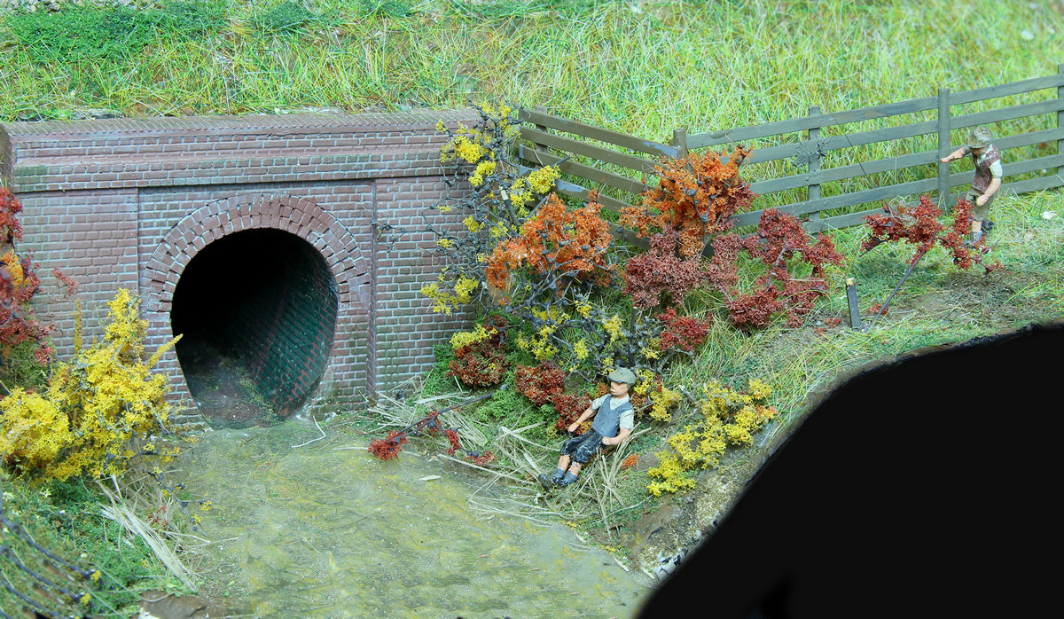 We’ve been wondering how to give the stream bed north of the culvert a bit more realistic shape, and while rooting round in my box of scenic bits and pieces, came across an unopened packet of ‘Das’ modelling clay, which must be at least 30 years old. Amazingly, it is still usable, so has been applied to the stream bed and banks to give the necessary shape. The entry into the culvert has been completed with water and other autumnal scenic detail added.
I’ve at last made a start on the signal box.