


March 2013. This month seems to have gone very quickly, with seemingly not a huge amount of progress. We have finished fixing the cosmetic chairs and the slide chairs, as well as starting work on fitting the tie bars. The main area of progress has been painting the sides of the rails a rusty colour - not the most interesting of tasks, but complete now.
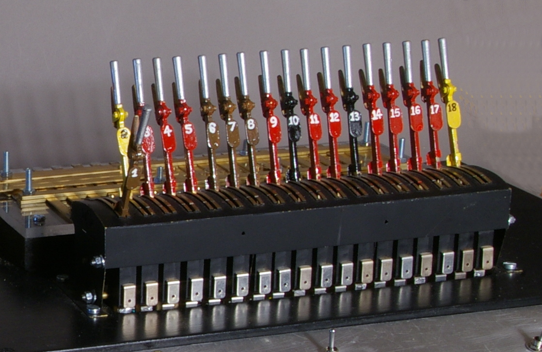
I haven’t made a lot of progress on the lever frame - the main thing left is to make the catch handles and catch boxes for the signal box frame.
Chris has started work on the footbridge. We have a Churchward Models kit, which is a pretty good representation of the bridge at Plumpton - and as good as we can get I think, without scratchbuilding.
I have worked out what I want to do with the base-boards, and we should be ready to start construction in May - hopefully it will be warmer by then,
Finally, I have drawn out my wiring diagram. The turnouts, signals and gates will be operated electrically from the lever frame, and in addition there will be switches for section control, Alex-Jackson electromagnets, and two sound modules for whistles. At some point in the future I intend to build block instruments and bells for communication with the fiddle yards, so I need to add some wiring for that as well.
The principles of my wiring are as follows:
- a control box containing transformers for various voltages (5V AC, 15V AC, and 21V DC) with separate transformers for the loco controllers. Mains power is restricted to this lockable box for safety, and is nowhere else on the layout (ie no mains powered transformers under the layout or control panel).
- 5V AC, 15 V AC, 21 V DC feeds to the control panel and all the baseboards to provide different voltages for different applications
- common earth for trackwork, so only one wire is required for each section
- a ‘control’ earth to be wired throughout the layout to provide the earth for the loco controllers (ie the common earth from the track)
- a separate ‘technical’ earth to provide a separate earth for turnout motors, AJ’s etc. The two earths are joined together at the control panel, and connected to mains earth. Experience shows that earthing all these functions together on the layout can cause back-feed through the loco controllers (so that locos move when turnouts are operated). Joining them together closer to mains earth avoids this problem.
- turnout and signal motors to be powered from either 5V AC or 15V AC line (depending on the motor), using diodes to switch polarity and hence reverse the direction of the motor. This requires only one wire from the lever frame to the motor.
- AJ’s powered from the 21V DC line.
- self isolating sidings, so that when a turnout is thrown against a siding, locos in that siding cannot run.
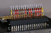
I’ve successfully used computer ‘D’ connectors on Brighton Road so will use the same technique again. These have the advantage of being relatively cheap, and in a variety of sizes (9, 15, 23 and 37 pin), but the pins are fairly fragile so care has to be taken when connecting the plugs and sockets. They are fine for relatively low current DC applications, but I don't know about DCC which uses higher current.
I like to use a coherent colour system for the wiring, so that as far as possible, the wire for a particular function (a turnout for example) is the same colour all the way from the lever frame to the motor. The cheapest way to get a large variety of coloured wire is to buy computer cable designed for the D connectors - for example 36 way cable, with 36 distinct colours, and to strip off the outer sleeving.
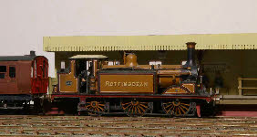
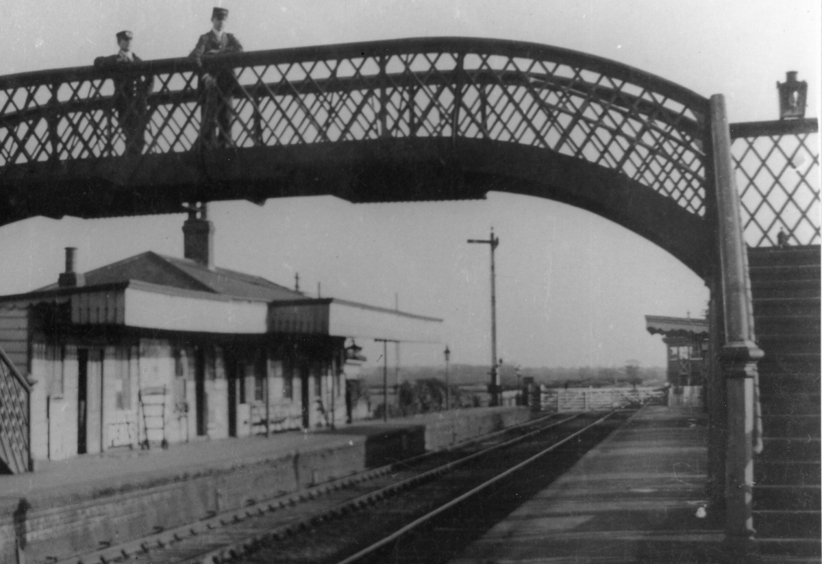
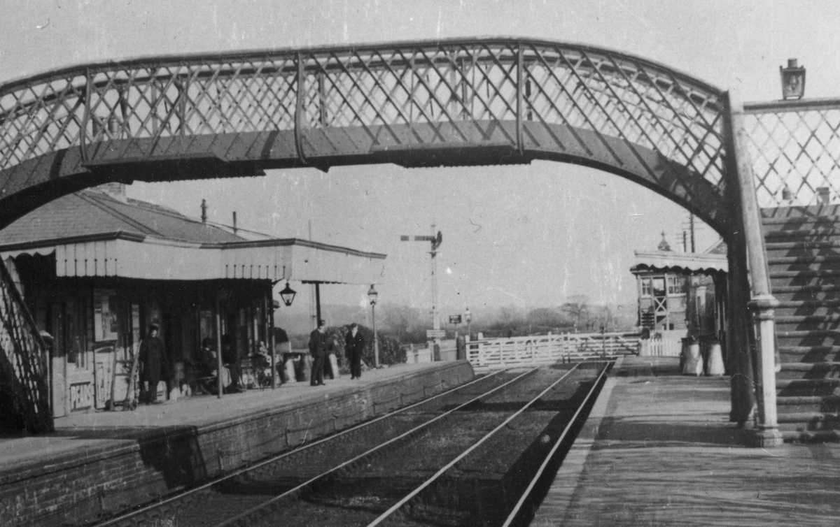
 I’ve also started to look at how to make the signals. The photographs left and right show two alternative height signals for the down platform starter -
 standard height, or very tall. The tall signal could be easily seen over the footbridge, but would be very difficult for the enginemen to see from below the signal, waiting for the right of way. The left hand, slightly out-of-focus, shot seems to show a tall signal with no ladder to get to the top of the post. However, there is a dark shape at about head height at the bottom of the post which could be a rotating lamp co-acting with the signal arm, to make it easier for the enginemen to see. More research needed I think, before I decide what to build.
April 2013. Not a lot done in April because of holidays. However, I have now finished the lever frames and locking frames, completing the catch handles, painting, final assembly, and adjustment of the locking frame. I’ve also fitted the microswitches, driven by the levers, which will activate the electric motors for points and signals.
 Having re-
assembled it, there are a few bits that needs a little adjustment, but nothing serious. I think the next phase is to actually use the lever frame, pulling levers appropriate for particular train movements, to make sure it is robust, and that nothing will break when it is finally wired up and attached to a functional model railway.
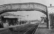
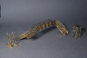 In addition to the lever frame, Chris has been working on the footbridge. It’s not an easy kit to build, but it is quite a complex prototype. However, progress has been made, and the over-
bridge and steps are more or less complete. The supporting stanchions on the real Plumpton footbridge are a little different from the kit, so a bit of scratchbuilding is required. The photo (right) shows the main span and supports more-or-less complete.
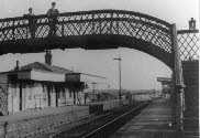
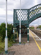 One rather curious feature is that the bracing wires on the stanchions are part buried in the platform surface (see photo left). I’m not sure why this would be, unless perhaps the original platform was considerably lower than it is today, and when platform heights were raised towards the end of the 19th century, the bridge was simply left in position, and the new platform surface built around it.
I haven’t made a lot of progress on the lever frame -
Chris has started work on the footbridge. We have a Churchward Models kit, which is a pretty good representation of the bridge at Plumpton -
I have worked out what I want to do with the base-
Finally, I have drawn out my wiring diagram. The turnouts, signals and gates will be operated electrically from the lever frame, and in addition there will be switches for section control, Alex-
The principles of my wiring are as follows:
-
I’ve successfully used computer ‘D’ connectors on Brighton Road so will use the same technique again. These have the advantage of being relatively cheap, and in a variety of sizes (9, 15, 23 and 37 pin), but the pins are fairly fragile so care has to be taken when connecting the plugs and sockets. They are fine for relatively low current DC applications, but I don't know about DCC which uses higher current.
I like to use a coherent colour system for the wiring, so that as far as possible, the wire for a particular function (a turnout for example) is the same colour all the way from the lever frame to the motor. The cheapest way to get a large variety of coloured wire is to buy computer cable designed for the D connectors -
 I’ve also started to look at how to make the signals. The photographs left and right show two alternative height signals for the down platform starter -
April 2013. Not a lot done in April because of holidays. However, I have now finished the lever frames and locking frames, completing the catch handles, painting, final assembly, and adjustment of the locking frame. I’ve also fitted the microswitches, driven by the levers, which will activate the electric motors for points and signals.
 Having re-
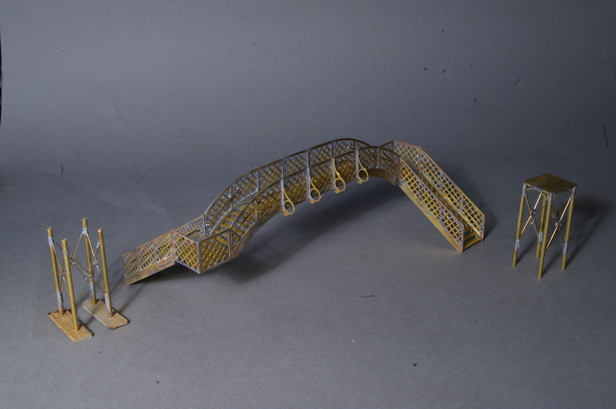 In addition to the lever frame, Chris has been working on the footbridge. It’s not an easy kit to build, but it is quite a complex prototype. However, progress has been made, and the over-
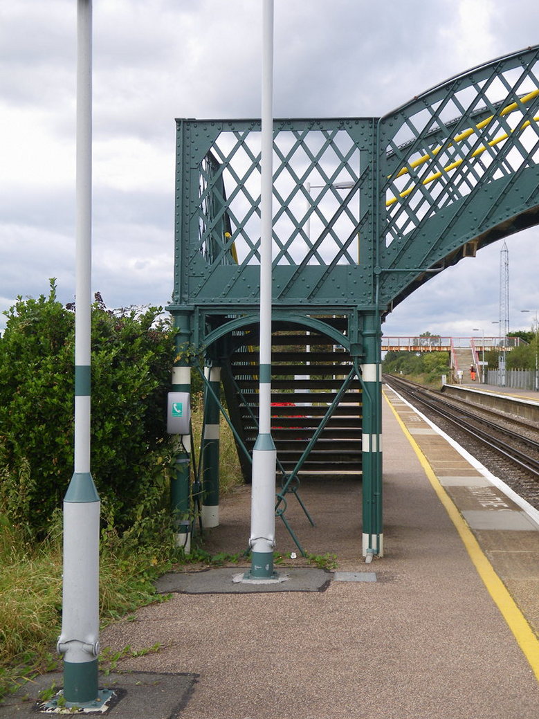 One rather curious feature is that the bracing wires on the stanchions are part buried in the platform surface (see photo left). I’m not sure why this would be, unless perhaps the original platform was considerably lower than it is today, and when platform heights were raised towards the end of the 19th century, the bridge was simply left in position, and the new platform surface built around it.