


November 2015 to February 2016
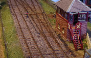
Now that the layout is reasonably ‘mature’, is working fairly reliably, and substantially complete, we are going back over the boards one by one to add some of the outstanding bits and pieces - not obviously missing, but absent nevertheless, starting with the Lewes end of the layout.
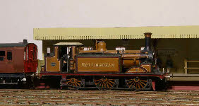
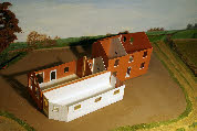
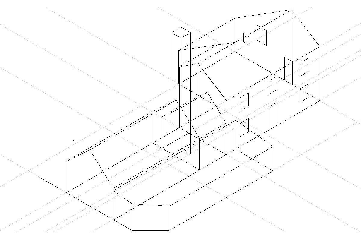
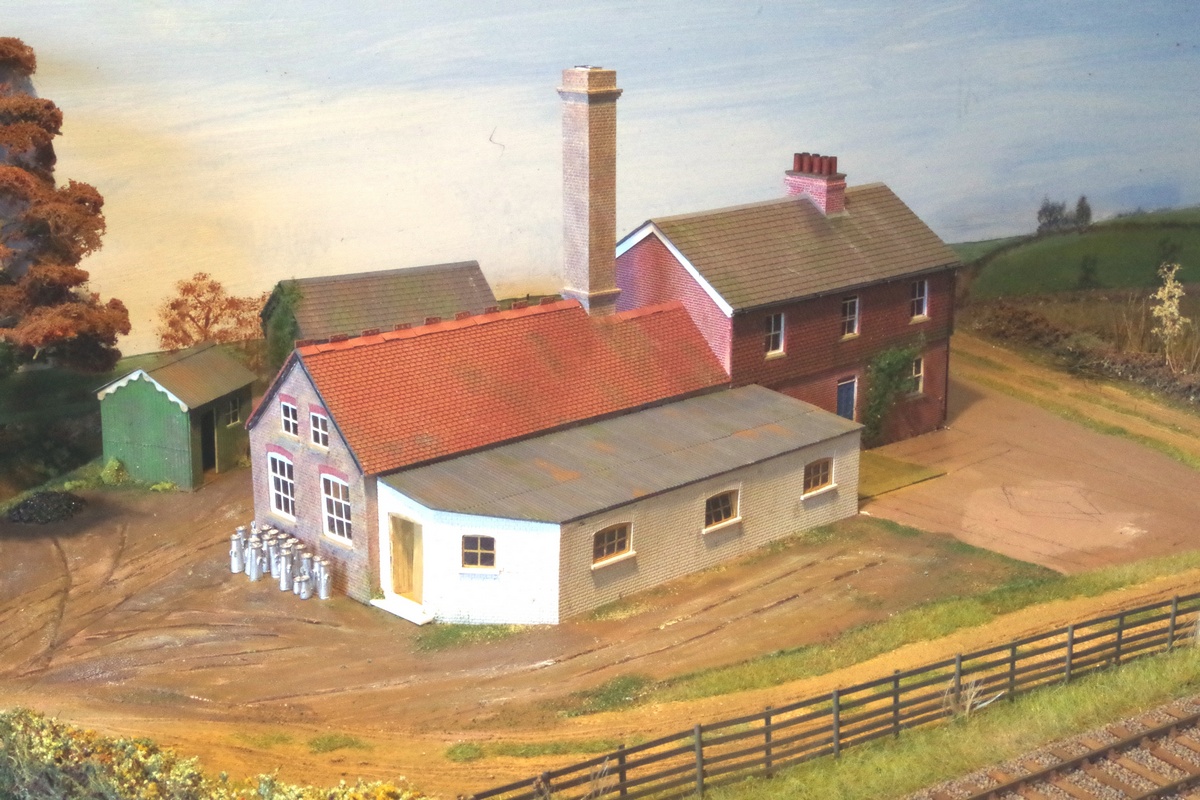
 Our start point has been to complete the creamery which fills a large scenic gap (photo right). I’ve drawn the building using 3D Turbocad so that we can see what the building will look like before cutting any materials. The mock-
up shown on the previous page has also helped correct a few minor errors.
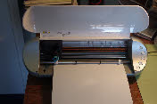 I’ve recently bought a ‘Silhouette’ flat bed cutter -
 intended primarily for cutting paper or card, but it works well with 5 or 10 thou plasticard, and is also capable of marking out thicker plasticard - Slaters embossed brick for example. Having drawn out the building in Turbocad, it’s relatively straightforward to turn this into drawings which the Silhouette can then use to mark out the plasticard.
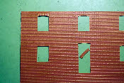
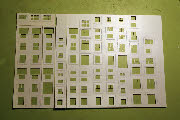 For cutting brick-
embossed plasticard I’ve used the cutter to mark out the window and door openings on the back of the plasticard (the smooth side), and have also included the brick arches over the windows (also marked out on the back of the plasticard). The photo above right shows the Silhouette in action, cutting out windows, and the photo (left) shows the sheet of windows on completion after removal of all the cut-away parts. The photo (right) shows one wall, having been marked out on the reverse by the Silhouette, and with all the openings subsequently cut out by hand. Two of the window arches have been cut out, turned over, and glued back in place. The doorway arch has been cut out and awaits gluing in place.
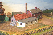 The next photo shows the building under construction, with all the walls in place, with a few windows, doors and sills added. Plasticard has a tendency to warp over time, so I have added balsa reinforcement along the tops of the walls and vertically between windows, fixed in with epoxy. A few of these pieces are in place, with a lot more to be added. The final photo shows the almost-
complete building (I forgot to add the curtains) with a lot of work remaining to be done around the building.

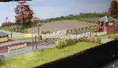
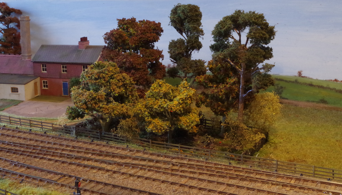
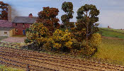 Whilst visiting the Uckfield show last year, we were able to order eight trees from Realistic Modelling Services -
 I think the last he made before retiring. These are all now in place in the little copse adjacent to the line, known locally as ‘Percy’s Patch’. This has transformed this area of the layout, as shown in the photos.
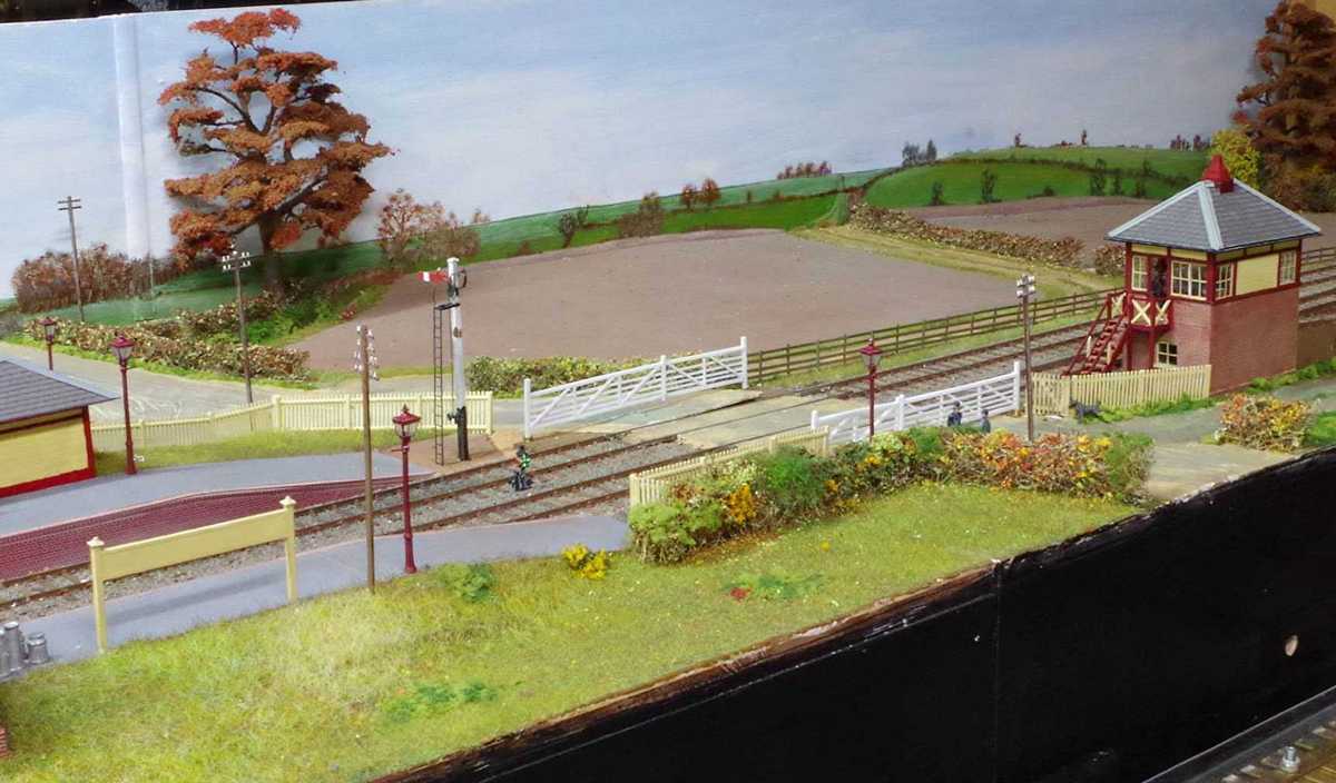
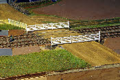 I made the first set of level crossing gates in early 2014, but didn’t get around to making them work at the time, partly because there were more urgent things to do to get the layout complete enough to exhibit, and partly because I hadn’t found a satisfactory way of making them work -
 not least because three of the four gates are on one baseboard, with the fourth on the adjacent board. The fact that the gates are severely skewed doesn’t make life any easier. However, with the completion of the creamery and the copse, the question of how to get the level crossing gates working arises again.
I’ve looked at various ways of purely mechanical operation, and also the use of Clearbox motor/gearbox combinations (used on the Brighton Road ground signals). None of these potential solutions seemed very practicable or robust, so no progress was made.
I’m familiar with servos in connection with my interest in flying radio controlled gliders, and subsequently came across their use in connection with rotating ground signals. After a considerable amount of experimentation I have arrived at a solution for the gates which seems to work well. Further detail is given here, and there is a short video here.
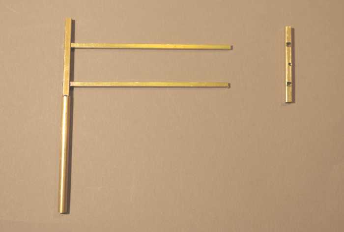
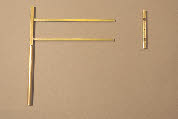 My initial attempt at making the gates proved not very robust. They were made entirely of Evergreen plastic section, but they warped a bit when glued together, and also proved to be a little fragile, especially the main post. My second attempt uses a brass frame (end-
posts and top and bottom rails) with the internal timbers made of plastic, superglued in place. The photo shows the components - the top and bottom rails are brass square section, mortised into the square tube end posts. The main post has a section of 1/8”brass rod soldered to its bottom end, to provide the pivot, and to connect to the servo under the baseboards.
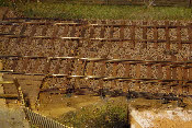
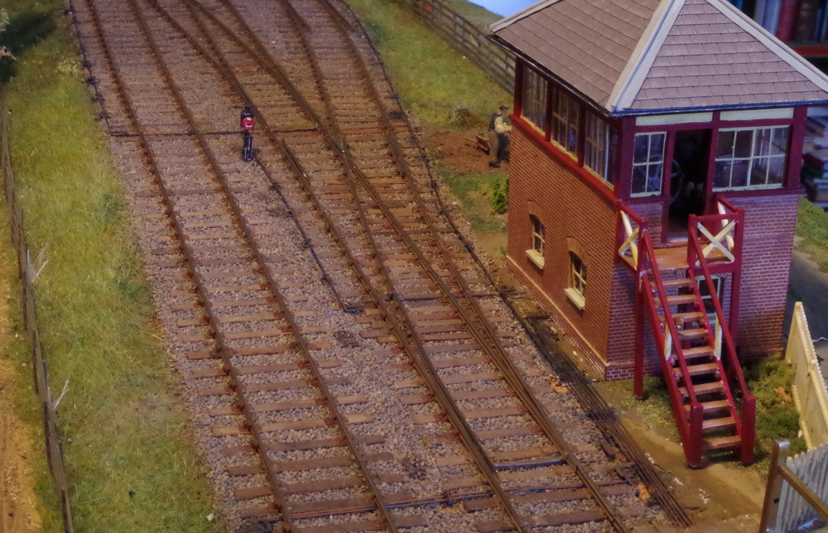
 Whilst working on this end of the layout, we have also added the last few missing chairs and all the fishplates. More importantly (or at least with more visible effect) we have made and installed all the point rodding associated with the signal box -
 just the boardwalk in front of the signal box to add.
We have a few sheets of Colin Waites’ rodding supports and also Brassmasters. I had a trial run making some of each, and concluded that both designs are extraordinarily fiddly and difficult to make. Eventually I opted for the Brassmasters’ design, partly because they are smaller, and I think closer to scale size than Colin Waites’ effort, but more realistically because I don’t think I have enough Colin Waites to finish the point rodding on both the signal box and the ground frame, and they are no longer available The Waites etches have been posted on eBay for some other lucky modeller to wrestle with.
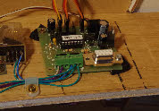
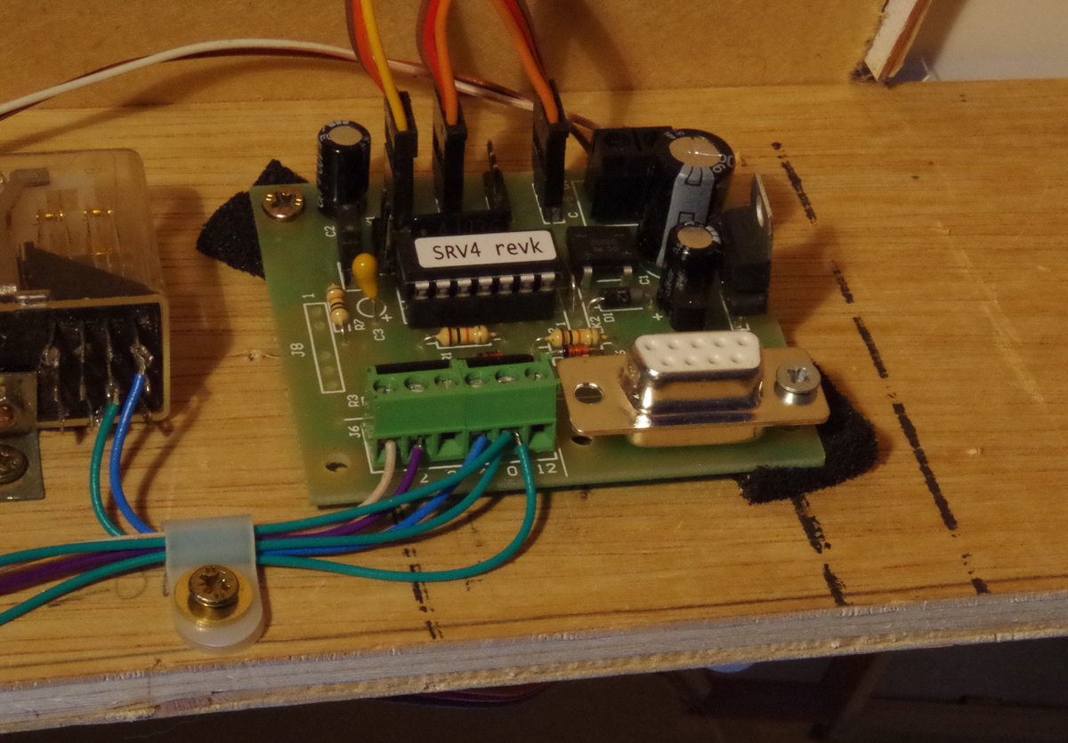
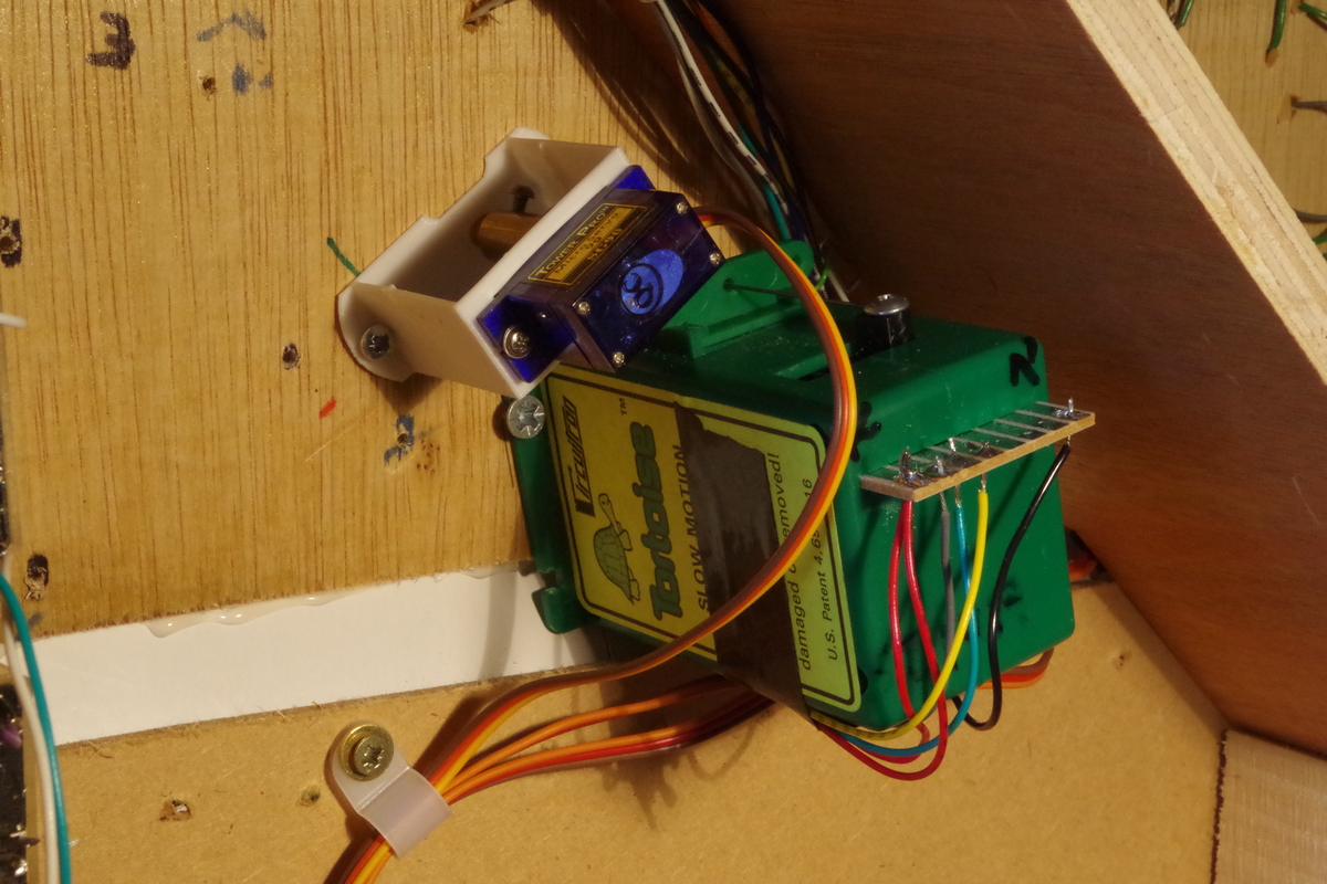
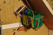 Finally, having got the electronics on the crossing gates working, we have turned my attention to the operation of the rotating ground signals. These have been through two versions so far: Fulgurex motors (too noisy) and Tortoise motors (difficult to adjust for 90 deg rotation). For the baseboard we’re working on, there are three ground signals, so a MERG Servo4 unit is ideal, easy to make and perfect for providing 90 deg rotation. The photo left shows the assembled kit in place under the base-
board, with one of the adjacent relays used to close the switch which operates one of the servos. The photo right shows one of the servos fixed in place by a slightly modified MERG servo mount - a useful comparison between the size of a servo, and a Tortoise motor. There is more detail here.
If you’re interested in using electronics devices to operate a model railway, have a look at the MERG website.
Now that the layout is reasonably ‘mature’, is working fairly reliably, and substantially complete, we are going back over the boards one by one to add some of the outstanding bits and pieces -
 Our start point has been to complete the creamery which fills a large scenic gap (photo right). I’ve drawn the building using 3D Turbocad so that we can see what the building will look like before cutting any materials. The mock-
 I’ve recently bought a ‘Silhouette’ flat bed cutter -
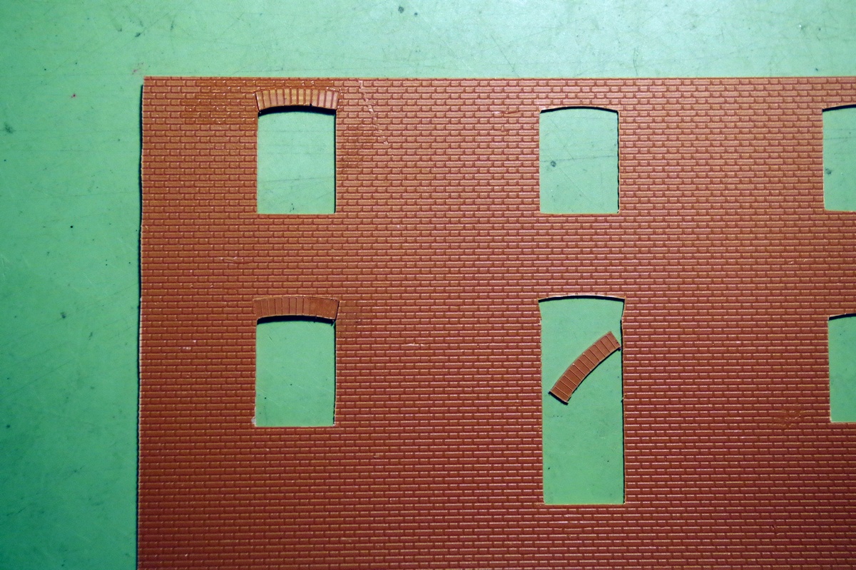
 For cutting brick-
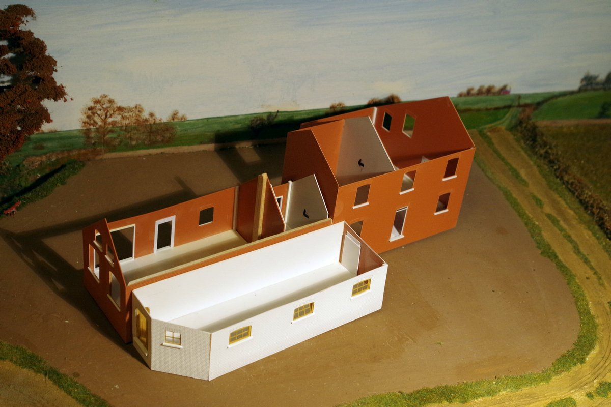
 The next photo shows the building under construction, with all the walls in place, with a few windows, doors and sills added. Plasticard has a tendency to warp over time, so I have added balsa reinforcement along the tops of the walls and vertically between windows, fixed in with epoxy. A few of these pieces are in place, with a lot more to be added. The final photo shows the almost-
 Whilst visiting the Uckfield show last year, we were able to order eight trees from Realistic Modelling Services -
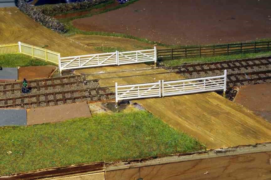 I made the first set of level crossing gates in early 2014, but didn’t get around to making them work at the time, partly because there were more urgent things to do to get the layout complete enough to exhibit, and partly because I hadn’t found a satisfactory way of making them work -
I’ve looked at various ways of purely mechanical operation, and also the use of Clearbox motor/gearbox combinations (used on the Brighton Road ground signals). None of these potential solutions seemed very practicable or robust, so no progress was made.
I’m familiar with servos in connection with my interest in flying radio controlled gliders, and subsequently came across their use in connection with rotating ground signals. After a considerable amount of experimentation I have arrived at a solution for the gates which seems to work well. Further detail is given here, and there is a short video here.
 My initial attempt at making the gates proved not very robust. They were made entirely of Evergreen plastic section, but they warped a bit when glued together, and also proved to be a little fragile, especially the main post. My second attempt uses a brass frame (end-
 Whilst working on this end of the layout, we have also added the last few missing chairs and all the fishplates. More importantly (or at least with more visible effect) we have made and installed all the point rodding associated with the signal box -
We have a few sheets of Colin Waites’ rodding supports and also Brassmasters. I had a trial run making some of each, and concluded that both designs are extraordinarily fiddly and difficult to make. Eventually I opted for the Brassmasters’ design, partly because they are smaller, and I think closer to scale size than Colin Waites’ effort, but more realistically because I don’t think I have enough Colin Waites to finish the point rodding on both the signal box and the ground frame, and they are no longer available The Waites etches have been posted on eBay for some other lucky modeller to wrestle with.
 Finally, having got the electronics on the crossing gates working, we have turned my attention to the operation of the rotating ground signals. These have been through two versions so far: Fulgurex motors (too noisy) and Tortoise motors (difficult to adjust for 90 deg rotation). For the baseboard we’re working on, there are three ground signals, so a MERG Servo4 unit is ideal, easy to make and perfect for providing 90 deg rotation. The photo left shows the assembled kit in place under the base-
If you’re interested in using electronics devices to operate a model railway, have a look at the MERG website.